
Subscribe to Our Youtube Channel
Related Manuals for 3i Corporation Pegasus Nx


Summary of Contents for 3i Corporation Pegasus Nx
-
Page 1: User Manual
User Manual ™ ©2013 3i-Corporation. All Rights Reserved. All trademarks belong to 3i-Corporation or its affiliated and subsidiary companies, all rights reserved. - Page 2 Pegasus™ NX User Manual | April 2013 © 2013 3i-Corporation and its affiliated and subsidiary companies, all rights reserved. All other trademarks are the property of 3i-Corporation and its affiliated and subsidiary companies. This product, including software, data and documentation are licensed to the user for its internal business purposes only and may not be disclosed, disseminated, sold, licensed, copied, reproduced, translated or transferred to any third party.
-
Page 3: Table Of Contents
Table of Contents Introduction ........................ 1 Scope ................................1 Audience ................................. 1 Contact Information or Comments ........................1 Text Conventions ............................. 2 Overview ........................3 About the User Manual ............................ 3 What is Pegasus™ NX? ..........................3 Technical Specifications ..................... 4 How Does Pegasus™... - Page 4 USB Mini B Port ............................. 19 Remote Configuration Alteration and Firmware Update ................. 19 Ethernet RJ45 LAN Port ..........................20 Customized Messages Related to Alarm Panel Events & Pegasus™ Occurrences ........20 Communication with Zeus™ Servers using Different Interfaces ..............21 Device Status via ECO SMS ..........................
-
Page 5: Introduction
Introduction Scope This User Manual is aimed in providing detailed information and complete listing as a reference to Pegasus™ NX and troubleshoot related issues. Audience This User Manual is intended for end users who are not familiar with Pegasus™ NX. Individuals involved in device troubleshooting should read this user manual. -
Page 6: Text Conventions
Text Conventions Begin Instruction: To begin a procedure under any topic. Use a numbered list for points under procedure. Note: Provides a message or reminder related to a topic or section. Warning: Information provided under this section MUST be followed. Several different sources of power can be connected to your Pegasus™... -
Page 7: Overview
Overview About the User Manual This User Manual is to describe the general information related to Pegasus™ NX along with technical specifications, woking process of the device and how to troubleshoot it during any issue. This User Manual also describes the various conditions and functionalities of LEDs. What is Pegasus™... -
Page 8: Technical Specifications
Technical Specifications Power Supply Input 9VDC – 15VDC Maximum 450mA Voltage Current Range Battery Battery Lithium-Polymer Battery Upto 6 hours depending on Type Backup network conditions Capacity: 2000mAh Processor ARM 32bit Cortex-M3 Speed 32Mhz Ethernet Network IEEE 802.3u compliant fast Ethernet CAT5 MDI/MDI-X auto Standard... - Page 9 GSM/GPRS Modem Quad-band EGSM 850 / SIM Card Dual SIM Support 900 / 1800 / 1900 MHz Holder Protocol TCP/IP or UDP/IP Antenna: Ω Support Impedance Antenna External Antenna: 2.0 dBi Type Peak Gain Dipole Antenna Module (DAM) Antenna: Antenna: -4.4 dB 824-960MHz,1710- Frequency...
- Page 10 Virtual Telephone Line Output Constant 25mA, 20V Current Source for Alarm Panel Telephone Line Connection Maximum 100VAC, 48VDC Minimum 3VDC Telephone Telephone Line Voltage Line Voltage Detection Detection PGMs 3 PGMs- Supporting 300mA sink 1 PGM- Supporting Open current per PGM SPDT Relay 125VAC/60VDC @2A Collector...
-
Page 11: Environmental Specifications
USB 2.0 Mini B USB USB Full 12 Mbit/s Device Speed Interface For Configuration, firmware upgradation and to view debug messages Tamper Switch Tamper Internal To trigger an event on Type unauthorized enclosure opening LEDs Power On First LED from top to GSM Status Fifth LED from top to Status... -
Page 12: Board Dimensions
Board Dimensions Length 82mm Thickness 1.6mm Width 80mm Number of Four Layers of Enclosure Dimensions Length 112mm Height 4.2mm Width 112mm... -
Page 13: How Does Pegasus™ Nx Work
How Does Pegasus™ NX Work? Pegasus™ NX acts as a communicator between the Alarm Panel that follows Contact ID Protocol and the Monitoring Station. Alarm Panel Event transmission is possible via Ethernet TCP/IP Network, Wi-Fi, and/or GPRS. The device is interfaced between the Alarm Panel and the telephone line (optional). -
Page 14: Pegasus™ Nx Features
Pegasus™ NX Features Telephone Line Cut Off Detection Pegasus™ NX is built-in telephone line cut off detector. This feature enables the device to detect telephone line cut off and send occurrences to the Zeus™ Server. To use this feature, in the Pegasus™ Studio – Configuration Tool, enable Telephone Line Cut OFF Detection. You can also configure the additional delay duration in telephone line cut off detection. -
Page 15: Alarm Panel Return Cut Off Detection
Alarm Panel Return Cut Off Detection Pegasus™ NX is built-in alarm panel return cut off detector. This feature enables the device to detect alarm panel return cut off and send occurrences to the Zeus™ Server. To use this feature, in the Pegasus™ Studio – Configuration Tool, enable Detect Alarm Panel Return Cut Off . You can also configure the additional delay duration in alarm panel return cut off detection. -
Page 16: Dual Sim Cards Support
Dual SIM Cards Support Pegasus™ NX is built-in dual SIM card holder. The dual sim card holder allows you to insert two SIM cards. You can use two SIM cards from the same or different service provider(s). These two SIM cards assist in GSM communication and have multiple functions: o Sending alive packets to the Primary and Secondary Zeus™... -
Page 17: Fixed Or Dynamic Ip (Dhcp)
Fixed or Dynamic IP (DHCP) Pegasus™ NX works efficiently with both Fixed/Static or Dynamic IP (DHCP) Addressing. Fixed/Static IP Addressing is for one customer on one IP address, whereas the Dynamic IP Addressing assigns a different IP Address each time the ISP customer logs on to their system, but this is dependent upon the Internet Service Provider (ISP) because some ISP's only change the IP address as they deem it necessary. -
Page 18: Four Zone Inputs
Four Zone Inputs Pegasus™ NX is built-in two zones which are extended to four zone inputs as shown in image. You can connect sensors or detectors to these zones. The device supports zone input wiring in both single-mode and double-mode. A sensor or detector can be connected in nine different ways. -
Page 19: Dual Communication Channels
Dual Communication Channels Pegasus™ NX can be used as a dual communication channel for any alarm panel that follows Contact ID Protocol. Generally, the device waits for events from alarm panel. If events are received, it validates each event by checking its Message Type, Event Qualifier and CRC. -
Page 20: Wi-Fi Connectivity
Wi-Fi Connectivity Pegasus™ NX is Wi-Fi supported and thus acts as a wireless alarm panel communicator. The Wi-Fi competence is one of the revolutionary features incorporated in Pegasus™ NX. Security systems have historically communicated over traditional telephone lines. As use of cellular phones and internet based communications is raising fast, traditional phone lines will not be around for much longer. -
Page 21: Inexpensive Resource
GSM Antenna Pegasus NX is built-in the RP-SMA GSM Antenna connected to the PCB mounted, right-angled RP-SMA RF Jack towards the right side. The Pegasus™ NX GSM Antenna is flexible with tilt and swivel design that can be adjusted as per the requirement. -
Page 22: Arm Or Disarm Alarm Panel Remotely
Arm or Disarm Alarm Panel Remotely Pegasus™ NX has two ways out that can be controlled remotely, and thus makes it possible to Arm or Disarm the Alarm Panel without using the telephone line, depending on the resource being available on different alarm panels. Tamper Monitoring &... -
Page 23: Maximum Alarm Panel Compatibility
Maximum Alarm Panel Compatibility Pegasus™ NX is compatible with any alarm panel that operates on Contact ID Protocol. Some well known alarm panels that work on the contact ID protocol and thus fully compatible with Pegasus™ NX are: Paradox, Honeywell Ademco, Bosch, Napco, Inhep, DSC, Logic, FBII, Inovanet, Rokonet, etc USB Mini B Port Pegasus™... -
Page 24: Ethernet Rj45 Lan Port
Ethernet RJ45 LAN Port Pegasus™ NX is built-in a RJ45 LAN port which can be used for high speed internet connectivity. Inside the socket eight metal strips at the bottom connect with corresponding strips in the plug. When the plug is inserted into the port it is locked into place by as plastic spring. -
Page 25: Communication With Zeus™ Servers Using Different Interfaces
The device reverts back with an ECO SMS related to its current status. Sample ECO SMS PEGASUS NX INF: PEGASUS OFFLINE, CURRENT INTERFACE: GPRS, PHONE LINE: CUT OFF, PNR: PRESEND, GSM SIGNAL: 26, JAMMER: OPERATIVE, ETH LINK: DOWN, WIFI: SSID CONNECTED Note: To use this feature, in the Pegasus™... -
Page 26: Anti-Sabotage Resource
Anti-Sabotage Resource Pegasus™ NX permits testing the alarm panel proper functioning and constant monitoring of the physical connection with the alarm panel, and thus acts as an anti-sabotage resource. Firmware Update Over-the-Air Pegasus™ NX is FOTA capable, firmware updates are issued directly over-the–air from the GSM service provider to the GSM modem. -
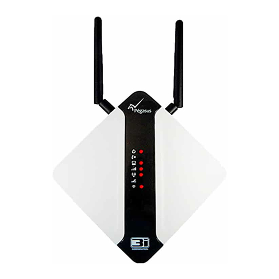
Page 27: How Does Leds Work
How Does LEDs Work? LEDs Description Pegasus™ NX is built-in seven on board LEDs that emits light to the Pegasus™ front cover and front panel via specially designed and secured LED pipes under specific conditions. - Page 28 LEDs Condition Function LED is OFF (a) Application is not running, module is not in the working state. Power ON LED is ON (a) Application is running, module is in the Status working state. LED is OFF (a) Telephone line is not connected to the module.
- Page 29 LEDs Condition Function LED is OFF (a) Alarm panel is not connected to the virtual line. Alarm LED is ON (a) Alarm panel is connected to the virtual line LED is OFF (a) Wi-Fi is not activated. (b) Module is not connected to internet via wi-fi. Wi-Fi Status LED is ON (a) Wi-Fi is activated.
-
Page 30: Troubleshooting Pegasus™ Nx
Troubleshooting Pegasus™ NX Troubleshooting Instructions Warning: DO NOT attempt to service your device. Opening or removing covers may expose you to dangerous voltages or other risks. Any servicing shall be referred to the trained 3i-Corporation® authorized service personnel only. Never troubleshoot the device during lightning or storm. Always use genuine 3i-Corporation®... -
Page 31: Gprs Transmission Related Issues
Case 2: Module Doesn’t Turn ON. Yellow LED (D12) does not light up. No messages Pegasus™ NX: Debug View Screen: are shown. How to troubleshoot or fix this problem? Problem might be caused by the LM2576 (voltage regulator) component malfunction. The general work voltage tune up of the device is responsible. -
Page 32: Pegasus™ Nx Doesn't Go Online By Gprs
How to troubleshoot or fix this problem? If the antenna is undamaged and correctly connected to the device, the problem will be solved by replacing the antenna pigtail. Pegasus™ NX Doesn’t Go Online by GPRS Case 1: Pegasus™ NX: Module doesn’t go online by GPRS. Green LED (D9) does not light up. It does not connect to the Zeus™... -
Page 33: Pegasus™ Nx Doesn't Go Online By Gprs/Ethernet
This also happens when a defective SIM CARD is placed in the holder causing a shortage. The SIM CARD replacement solves this problem. Case 3: : Module doesn’t go online by GPRS. Green LED (D9) does not light up. It does not connect to the Pegasus™... -
Page 34: Pegasus™ Nx Doesn't Receive Events Sent By Alarm Panel
Case 2: Module doesn’t go online by GPRS/Ethernet. Green LED (D9) does not light up. It does not connect Pegasus™ NX: to the Zeus™ server. A message is displayed saying, “The IDENTIFICATION packet was not recognized by the Debug View Screen: Primary Zeus™... - Page 35 Another message is displayed saying, “Phone off Hook” counter above 1, unless it sends an event (if it’s able to send)”. How to troubleshoot or fix this problem? If the TIP and RING terminals are connected properly, it can be the HT9170 (DTMF Decoder) component failure. When it reaches the 8th attempt, device switches the communication to the phone line and only returns after a restart or phone line failure.
-
Page 36: Pegasus™ Nx Doesn't Initialize
It can be easily verified by measuring the voltage (must be around 24V) between TIP and RING connections. Case 4: Module doesn’t receive events sent by Alarm Panel. Received events are in wrong Zeus™ Server: Pegasus™ NX: format (client and/or code mismatch). A message is displayed saying, “Dialed phone number is not the one configured on alarm Debug View Screen: panel”. - Page 37 This issue is related to the flash memory failure. Identified component must be replaced. Case 5: Module doesn’t initialize. Pegasus NX: A message is displayed saying, “Initializing test routine of RTL8019 (It may take a few seconds) - Tera Term: Warning: Cannot locate a RTL8019”.
-
Page 38: Softwares Related To Pegasus™ Nx
Softwares Related to Pegasus™ NX Zeus™ Server The Zeus™ Server is the main element in the system. It is a multi-task software which offers many functionalities. It receives communication coming from Pegasus™ NX via data network and thus manages the device by detecting anomalous situations: communication loss, telephone line cut, low signal level, internal failure, communication loss with alarm panels, etc. -
Page 39: Pegasus™ Studio - Configuration Tool
Receiver is directly connected to the Zeus™ server. It supports information cryptography and its undoing, internet connection loss detection, database backup and automatic zipping. Pegasus™ Studio – Configuration Tool The Pegasus™ Studio is a state-of-art installable application to assist you to accomplish Pegasus™ NX related configuration settings. -
Page 40: Remote Debugger
Remote Debugger Remote Debugger is a handy application for log message monitoring that makes the distant monitoring of Pegasus™ NX functioning messages possible. This tool, in most cases, permits diagnosing what is happening to Pegasus™ NX without moving it to any specific location. The Remote Debugger monitors log messages sent throught WINAPI OutputDebugString or WM_COPYDATA message. -
Page 41: Accessories
Accessories Pegasus™ CSD Receiver The Pegasus™ CSD Receiver is a two-channel CSD cellular receiver which gives your Pegasus™ NX a 3rd communication channel, making it possible for them to transmit the events to a monitoring base even when the GPRS network and/or the Internet event reception link is off line and if the monitored client’s telephone line is cut. -
Page 42: Antennas
Antennas... -
Page 43: Appendix
Appendix Abbreviation Global System for Mobile Subscriber Identity Module Communications GPRS General Packet Radio Service Wi-Fi Wireless Fidelity DHCP Dynamic Host Configuration Wi-Fi Protected Access Protocol Short Message Service Wired Equivalent Privacy Domain Name Service WPA2 Wi-Fi Protected Access version MAC Address Media Access Control Address IP Address...
Need help?
Do you have a question about the Pegasus Nx and is the answer not in the manual?
Questions and answers