Table of Contents
Advertisement
Quick Links
Advertisement
Table of Contents

Summary of Contents for HARVARD H407
- Page 1 H407 OWNER’S MANUAL 40-Channel FM Base Station Citizenband Transceiver H407...
-
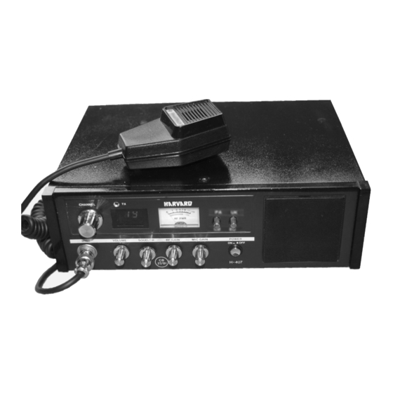
Page 2: General Description
Volume, Squelch, and Transmit Indicator Light. TRANSMITTER The heart of your H407 is the all new PLL oscillator. It provides full 40 channel operation from only one crystal. Integrated circuits plus other components replace the balance of crystal. PLL is the most accurate frequency system available for CB,... - Page 3 - 3 -...
- Page 4 RF Gain to avoid overload or distortion or interference from adjacent channels. PA-CB SWITCH When the PA/CB switch is placed in the PA position, it converts your H407 into a powerful Public Address System. The "PA" function requires an optional 8-16 ohm paging speaker.
- Page 5 CHANNEL 9 PRIORITY SWITCH When this twitch It pushed, channel 9 will be displayed on LED display and set will operate only on "Emergency Channel 9". N/B: Channel 9 is the national recognised "Emergency Channel". Use this channel only in cases of emergency. TRANSMIT LIGHT This light gives you a visual indication of the transmit mode.
-
Page 6: Specifications
SPECIFICATIONS GENERAL 18 transistors, 2 FET, 28 diodes, 4 integrated 1. Semiconductors circuits 3 inch, 8 ohms voice coil 2. Self-Contained Speaker Dynamic microphone with push-to-talk switch, 3. Microphone 500 ohms Volume control 4. Controls, Indicators and Variable Mike Gain Control Connectors Variable Squelch Control Variable RF Gain Control... -
Page 7: Transmitter Section
SPECIFICATIONS TRANSMITTER SECTION 4 watts (MPT-1320) a. RF Output Power ±2.5 KHz max. b. Freq. Deviation (@1 KHz) c. Audio Freq. Response dB per 6dB/OCT at 0.3-3.0 Khz pre-emphasise d. Spurious Emission less than 50nw 80 - 86 Mhz 87.5 -118 Mhz 135-136 Mhz 174-230 Mhz 470 - 862 Mhz... -
Page 8: Antenna Connection
POWER SUPPLY DC OPERATION: While It is highly unlikely that you will use your H407 in an automobile, you may desire to run it off a 12 Volt battery in case of emergencies. You can do this by attaching the DC cord to the set. Attach the red (fused) wire to the battery plus (+) terminal. -
Page 9: Antenna Requirement
ANTENNA REQUIREMENT This transceiver will operate with any standard 52 ohm ground-plane, vertical, mobile whip, long wire or other CB antenna. A standard 80-239 type connector is provided on the back panel for use with popular PL-259 antenna plug. ANTENNA INSTALLATION BASE STATION: When the H-407 is used as a base station, any Citizens Band beam, dipole, ground plane or vertical antenna may be used. -
Page 10: Mobile Installation
MOBILE INSTALLATION A location in the car or truck should be chosen carefully for convenience of operation and non-interference with normal driving functions. Mounting may be under the dash or instrument panel or any place a secure installation can be made, The 12-Volt cable may be connected to any convenient terminal, but preferably to the ignition switch to prevent unauthorized persons from operation of your unit. -
Page 11: Operating Procedures
With no signal present, rotate Squelch control clockwise until the rushing noise disappears. TRANSMITTER CAUTION: NEVER OPERATE YOUR H407 WITHOUT AN ADEQUATE ANTENNA SYSTEM OR LOAD. ANTENNA SWR SHOULD NOT EXCEED 3:1. FAILURE TO FOLLOW THIS RECOMMENDATIONS COULD RESULT IN UNIT DAMAGE. -
Page 12: Coaxial Cable
YOU AND YOUR ANTENNA Three main components comprise a typical Cltizens band installation. They are: the transceiver, an antenna, and the coaxial cable which connects the antenna to the transceiver. It is important that all three pieces are installed correctly to give he best possible range and reliable performance. -
Page 13: Tuning Your Antenna
Power Losses 1.3:1 1.5:1 1.7:1 10:1 TUNING YOUR ANTENNA For optimum performance, an SWR meter should be used to tune the antenna. However, since these meters can be EXPENSIVE, not everyone may want to invest in a purchase. If possible, borrow one, If you are unable to borrow one, the RF output meter on your transceiver can be used as a GUIDE to antenna tuning. - Page 14 B. TUNING YOUR ANTENNA WITH AN SWR METER Using an SWR meter is the most accurate way to tune an antenna. Connect the SWR meter as close as possible to the back of the transceiver. Use a double male connector or a very short piece of RG58/U with connectors on each end. Place the adjustable whip halfway into its receptacle.
-
Page 15: Helpful Hints
HELPFUL HINTS High SWR robs you of range and puts a strain on your output transistor. ALWAYS TUNE A NEW ANTENNA. Never tune your antenna in a closed area (garage, under a metal car port, etc.) incorrect tuning may result. MAKE SURE ALL MECHANICAL CONNECTIONS ARE TIGHT.
Need help?
Do you have a question about the H407 and is the answer not in the manual?
Questions and answers