
Related Manuals for Duro 6200 SXT

Summary of Contents for Duro 6200 SXT
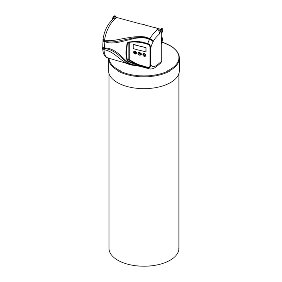
- Page 1 Operating and Service Manual 6200 SXT Automatic Backwashing Filter Activated Carbon For Chlorine and Bad Taste and Odor Reduction Multimedia For Turbidity Reduction Neutralizer For Acidic Water Made in Canada...
-
Page 2: Read This Manual First
Introduction Read this Manual First • Read this manual thoroughly to become familiar with the device and its capabilities before installing or operating your Water Filter. Failure to follow instructions in this manual could result in personal injury or property damage. This manual will also help you to get the most out of your filter. -
Page 3: Basic Principles
Basic Principles The success of the installation will depend, to a great extent, on advanced planning and preparation. Careful attention to the location of the unit, accessibility to electrical and drain facilities, and the availability of the proper tools will ensure a professional-looking installation. -
Page 4: Specification
Specification Working Temperature = 34-110°F (1-43°C) Service Peak Service Backwash Shipping (Do not subject the unit to freezing temperatures) Unit Media Flow Rate Flow Rate Flow Rate Weight Working Pressure = 20-125 PSIG (137-861 kPa) Voltage = 120V / 60 Hz Item # Model # Tank Size... - Page 5 How a Duro Automatic Backwashing Filter Works Raw water enters your home through the main supply line, enters your filter, and passes downward through the media bed Impurities such as turbidity and sediment (MMF) and organics (ACF) are removed from the water. The filtered water then flows up and into your household water lines.
- Page 6 Familiarize Yourself with the Unit and Components Control Valve Tank Jacket Tank Media Bed Distributor/Riser...
-
Page 7: Installation Instructions
Installation Instructions Contact your local distributor to use WaterGroup laboratory for complete water analysis free of cost and no obligation to you. All government codes and regulations governing the installation of these devices must be observed. If the ground from the electrical panel or breaker box to the water meter or underground copper pipe is tied to the copper water lines and these lines are cut during installation of the Noryl bypass valve and/or poly pipe, an approved grounding strap must be used between the two lines that have been cut in order to main- tain continuity. - Page 8 Figure 1b: Mulit Media Filter (MMF) Typical Installation Electrical Panel Hard Filtered Cold Soft Water Water Hard Soft Water Ground Strap Raw Water To Outdoors Drain Drain Water Meter Multi Media Taste and Odor Softener Water Heater Filter (MMF) (ACF) Filter Figure 1c: Neutralizing Filter (NF) Typical Installation Hard...
- Page 9 Figure 2 Unfiltered Water Bypass Ground Strap Required Loop Cut & Capped Because of Break in Continuity Filtered Water Line in Home Preparations 1. Determine the best location for your water filter, bearing Hard Electrical Panel Cold Soft Water Filtered in mind the location of your water supply lines, drain line ...
- Page 10 Neutralizing Multi Media Activated Filter (NF) Filter (MMF) Carbon Filter Media Bed Media Bed (ACF) Media Calcium Anthrafilt / Carbonate & Anthracite Magnesium Carbon (Black) Oxide (Black) Fine Sand Mixed (Grey / White) Fine Garnet (Purple) Coarse Garnet (Purple) Support Bed Support Bed Support Bed (when supplied)
- Page 11 Dome Hole Cap dome hole removed. CAUTION: make sure the O-Ring is free of defects. Use silicone based lubrication (part # 92360) if neccesary CAUTION! Make sure that the unit is de-pressurized before conducting this task. DO NOT use petroleum based lubricants as they will cause swelling of O-ring seals. The filter is now charged with media.
-
Page 12: Installation Steps
Installation Steps: 1. Clamp Ring – The clamp ring con- nects the control valve to the tank and provide an easy way to discon- nect tank during control valve servic- ing. Make sure that the clamp ring screw is tightened. The “Clamp Ring”... - Page 13 4. Attach the bypass valve to the con- trol valve (and yoke if plastic bypass is used). Connect the inlet and outlet Make sure that the flow of the water softener to the plumb- meter is connected to the ing in the house.
- Page 14 outlet intlet 6. Make sure the bypass valve is in the 7. Plug the 24-volt transformer into a service position. 120 VAC 60 Hz outlet. Circuit Board Screen Position Label Brine Cam 8. This valve has two positions: 1) The valve position during regenera- Cycle Step Abbreviation...
-
Page 15: Water Conditioner Flow Diagrams
Water Conditioner Flow Diagrams Service Position Backwash Position Filtered Water Filtered Water Raw Water Raw Water Hard Water Soft Water Hard Water Soft Water To Drain To Drain To Drain 9. Press to advance the valve to the “1” Backwash po- 10. -
Page 16: Programming Instructions
Programming Instructions Set Time of Day Press and hold buttons until display reads TD Adjust the displayed time with buttons. Press to resume normal operation Queuing a Regeneration 1. Press the button. The service icon will flash to indicate that a regeneration is queued. 2. -
Page 17: Diagnostic Programming Mode
Diagnostic Programming Mode Diagnostic Programming Mode Options Abbreviation Parameter Description Flow Rate Displays the current outlet flow rate Peak Flow Rate Displays the highest flow rate measured since the last regeneration Hours in Service Displays the total hours that the unit has been in service Volume Used Displays the total volume of water treated by the unit Displays the system’s reserve capacity calculated from the system... - Page 18 Controller Behavior Control Operation During Programming The control will only enter the Program Mode with the valve in Service. While in the Program Mode, the control will continue to operate normally, monitoring days and keeping all displays up to date. Control programming is stored in memory permanently, eliminating the need for battery back-up power.
-
Page 19: During Regeneration
During Regeneration Automatic Bypass The regeneration cycle lasts approximately 15 minutes, after which treated water service will be restored. During regenera- tion, untreated water is automatically bypassed for use in the household. Hot water should be used as little as possible dur- ing this time to prevent hard water from filling the water heater. -
Page 20: Maintenance Instructions
Maintenance Instructions Care of Your Filter To retain the attractive appearance of your new water filter, clean occasionally with a mild soap solution. Do not use abrasive cleaners, ammonia or solvents. Never subject your softener to freezing or to temperatures above 43°C (110°F). Servicing Components. - Page 21 6200 Service Kits – Piston and Cartridge Assembly Dwg # Part # Part Description O-Ring 97 61799-01 Cartridge Assembly with Piston O-Ring 98 11335 Screw, 4-40X3/16 Blank 16394 O-Ring, 029 REVISIONS APP'D 13287 O-Ring, 123 ZONE REV. DESCRIPTION DATE Blank 61799 Seal and Spacer Cartridge 42920...
- Page 22 6200 Service Kits – Flow Meter (Optional) Dwg # Part # Part Description 19791-01 Cable, Meter 19569 Clip, Flow Meter 13314 Screw, Slot Hex, 8-18 X0.6 19797 Meter, Assy,3 /4" Dual Port 13305 O-Ring, -119 14613 Flow Straightener 60626 Meter Only, Electronic Turbine 6200 Service Kits –...
- Page 23 6200 Service Kits – Other Parts Dwg # Part # Part Description 17020 Screw, Stl Hex, 6-20 X 3/8 040050 Screw, Hex Washer 42919 Cam, Brine 43107 Label, Cam Position, Softener 43121 Label, Cam Position, Filter 13314 Screw, Slot, Hex, 8-18 X 0.60 18280 Collector, Top, 1"...
- Page 24 6200 Service Kits – Other Parts Continued Dwg # Part # Part Description 19998 Shaft, Drive 40057 Screw, Hex Washer Head 40254 Clamp, Ring 60503 Clamp Ring Assembly Bypass Valve Assembly & Yokes (Plastic) Item No. Quantity Part No. Description 13305 O-ring, -119 13255...
-
Page 25: Timer Replacement
Timer Replacement Meter Cable Screw Self tapping screw Screw Brine Valve Brine Cam Bracket 1. Disconnect the meter cable from the 2. Open the front cover of the control 3. Remove the two screws from the meter. (If flow meter is attached) valve, unscrew the brine cam and grey brine valve bracket and push the brine valve in order to... - Page 26 Piston Cartridge Assembly Replacement All 5 O-rings need to be inspected for damages REVISIONS ZONE REV. DESCRIPTION DATE APP'D and lubricated LAST SAVED IN SMARTEAM: DATE AND TIME CRITICALITY SYMBOLS PER QPSP-001.2 THE COMPONENT, PART, OR ASSEMBLY DESCRIBED IN THIS DOCUMENT MUST COMPLY WITH THE EU (EUROPEAN UNION) DIRECTIVE: RoHS DIRECTIVE 2002/95/EC, LEVEL I LEVEL II...
- Page 27 Servicing and Replacing Drain line Flow Control (DlFC) 1. Disconnect the drain line retainer clip. 2. Remove the DLFC assembly and pull the flow washer out DLFC of the DLFC housing with then help of plier. Retainer 3. Remove the flow washer from the housing and clean it with water to remove any debris.
-
Page 28: Circuit Board Replacement
Circuit Board Replacement Screws Meter Cable Power Harness 1. Detach the circuit board from valve 2. Disconnect the meter cable and 3. Replace and connect the new front cover by removing two screws. power head harness from the circuit circuit board on the front cover. board. - Page 29 6200 SXT Valve Dimensional Drawings All dimensions are in Inches (mm).
-
Page 30: Parts Breakdown
Parts Breakdown Activated Carbon Filters (ACF) Part Number Model Distributor (1) Valve (2) Tank (3) Media Bed (4) Tank Jacket (5) 4628 DACF75SXT 19478 6200211 18474 95401 100502 4629 DACF10SXT 19478 6200212 110474 95402 100507 4630 DACF15SXT 19477 6200213 112524 95403 4631 DACF20SXT... -
Page 31: Parts Dimensions
Parts Dimensions Dimesions (inches) DACF75SXT/ DACF15SXT/ DMMF75SXT/ DMMF20SXT/ DMMF10SXT/ DMMF15SXT/ DNF75SXT DACF10SXT DNF20SXT DACF20SXT DNF10SXT DNF15SXT... -
Page 32: Troubleshooting Guide
Trouble Shooting guide Error Codes Note: Error codes appear on the In Service display Error Code Probable Cause Recover and Resetting [Err 0] Drive motor is stalled Unplug the unit from the power source [Err 1] Drive motor is running continuously When power is restored to the unit, the Err _ display code clears. If the condition causing the error has not been resolved the Err _ code reappears in the four digit display. Do not attempt to troubleshoot this problem any further. [Err 2] There have been more than 99 days since Regeneration must occur for the unit to recover, the the last Regeneration. If the Day of the Week display to clear and the valve to mode of regeneration is selected and days function normally. since last regeneration exceeds 7 days. [ 7 - - 5 ]: To recover from [Err2], the user must [ 7 - - 5 ]: There have been more than 7 days initiate a regeneration or set at least one individual since the last regeneration. All individual day to 1. settings (d1, d2, d3, d4, d5, d6, d7) are set to [Err 3] Control board memory failure. Perform a Master Reset. If the error returns, do not attempt to troubleshoot this problem any further. - Page 33 Trouble Shooting guide Problem Cause Correction 1. Filter bleeds taste and odor A. Bypass valve is open A. Close bypass valve or sediment B. Electrical service to unit has B. Assure permanent electrical service (check fuse, plug or switch) been interrupted C.
-
Page 34: General Provisions
Duro Guarantee WaterGroup Inc. guarantees that your new water conditioner is built of quality material and workmanship. When properly installed and maintained, it will give years of trouble free service. Seven Year Complete Parts Guarantee: WaterGroup Inc. will replace any part which fails within 60 months from date of manufacture, as indicated by the serial number provided the failure is due to a defect in material or workmanship. The only exception shall be when proof of purchase or installation is provided and then the warranty period shall be from the date thereof. Ten Year Guarantee on Mineral Tanks and Brine Tanks: WaterGroup Inc. will provide a replacement mineral tank or brine tank to any original equipment purchaser in possession of a tank that fails within 120 months, provided that the water conditioner is at all times operated in accordance with specifications and not subject to freezing. General Provisions: WaterGroup Inc. assumes no responsibility for consequential damage, labor or expense incurred as a result of a defect or for failure to meet the terms of these guarantees because of circumstances beyond its control. - Page 35 U.S. Headquarters WaterGroup Companies, Inc. 193 Osborne Road Fridley, MN 55432, USA 1-877-581-1833 TOLL FREE PHONE: Canada Headquarters WaterGroup Companies, Inc. 490 Pinebush Road, Unit 1 Cambridge, ON N1T 0A5, Canada 1-877-288-9888 TOLL FREE PHONE: www.watergroup.com Distribution locations Durham, NC Libertyville, IL Pottstown, PA Rancho Cucamonga, CA...
Need help?
Do you have a question about the 6200 SXT and is the answer not in the manual?
Questions and answers