Table of Contents
Advertisement
Quick Links
Advertisement
Table of Contents

Subscribe to Our Youtube Channel
Related Manuals for RC Logger Xtreme 88007RC

Summary of Contents for RC Logger Xtreme 88007RC
- Page 1 Operating instructions 88007RC (Mode 1) 88008RC (Mode 2) 88009RC (ArF) Xtreme...
- Page 2 EVER WONDERED WHAT INNOVATION LOOKS LIKE? Xtreme.
-
Page 3: Table Of Contents
8.4.2 LiPo batteries ..............11 15.5 Storage .....................21 8.5 Miscellaneous ...................13 16. TRANSMITTER ..............22 PRODUCT DESCRIPTION ............13 16.1 RC Logger transmitter...............22 16.1.1 Mode 1 ................22 10. YOUR XTREME ..............14 16.1.2 Mode 2 ................24 11. DIMENSIONS ..............16 16.1.3 Binding ................26 16.1.4 FHSS – Frequency hopping ...........26 12. - Page 4 16.3 RC Logger OneLINK .................26 17.3.3 Double-sided tape ............41 16.3.1 Preparation ..............27 17.3.4 Alternative mounting methods ........41 16.3.2 Mounting the OneLINK to your transmitter .....27 17.4 Trigger port/channel ................41 16.3.3 Preparing your OneLINK for Spektrum transmitters ..27 17.4.1 Introduction ..............41 16.3.4 Important notes in regards to learning the OneLINK ..28...
- Page 5 20. DISPOSAL ................55 18.5.5 Starting the motors ............47 18.5.6 Directional checks ............47 20.1 General .....................55 18.5.7 Taking off .................47 20.2 Batteries ....................55 18.5.8 Landing ................48 21. FCC COMPLIANCE STATEMENT ........55 18.5.9 Trimming .................48 18.5.10 Gradual learning .............48 22. PRODUCT SUPPORT ............55 18.5.11 Turning off ...............48 23.
-
Page 6: Introduction
1. INTRODUCTION 2. LATEST OPERATING INSTRUCTIONS Dear customer, ENGLISH: Please download the latest version of the operating instructions from our website at www.rclogger.com. Navigate Thank you for making the excellent decision to purchase this RC Logger product. You now ® to the product page and open the ”Downloads” tab. Click on have a high-quality product with a name that represents outstanding products. -
Page 7: Intended Use
4. INTENDED USE 5. DELIVERY CONTENTS The »Xtreme is a toy model quad copter solely designed for private use in the model 1 x RC EYE One Xtreme making area and the operating times associated with this. The »Xtreme is not suitable for 1 x Transmitter (Not available for the ArF version) other types of use, including commercial applications. 1 x LiPo Battery (800 mAh) Any use other than the one described can damage the device. Moreover, this involves 1 x USB Charger... -
Page 8: Spare Parts
89062RC Xtreme Case 1 x Back holder with DIN size tripod screw 1 x Antenna switch cable (to SMA female) 1 x Xtreme Case 1 x Operating instructions 1 x Carrying Strap 89042RC RC EYE OneCam 5.8 GHz FPV Kit 89080RC Xtreme Adaptor Cable (for OneCam) 1 x Adaptors Set 1 x RC EYE OneCam TX 1 x Operation Manual 1 x RC EYE OneCam 5.8 GHz RX 89041RC RC EYE OneStation 1 x RC EYE OneStation 7. SPARE PARTS 1 x Operating instructions 89036RC RC EYE OneLINK 89065RC Xtreme Canopy (Red) 1 x RC EYE OneLINK 1 x Xtreme Canopy (Red) 1 x Connecting cable for Futaba... - Page 9 89070RC Xtreme Flight Control Board 89075RC Xtreme Motor 1 x PCBA 1 x Xtreme Motor (Pre-mounted on the holder) 2 x Plastic Washer (top) 89076RC Xtreme Replacement LED Set 2 x Plastic Washer (bottom) 3 x LED Light (red, green and white) 2 x Washer (ø 0.13 x 0.02 inches) (ø 3.2 x 0.5 mm) 89077RC Xtreme Small Parts Set 2 x Screw (ø 0.07 x 0.2 inches) (ø 1.7 x 5 mm) 4 x Screw (PM2 x 16 mm) 2 x Screw (ø 0.06 x 0.28 inches) (ø 1.4 x 7 mm) 2 x Screw (ø 0.06 x 0.28 inches) (ø 1.4 x 7 mm) 89071RC Xtreme Propeller Set (138 mm) 2 x Screw (ø 0.07 x 0.2 inches) (ø 1.7 x 5 mm) 4 x 5.43 inches (138 mm) Propellers (2 Red and 2 Black) 2 x Screw (PM2 x 8 mm) 2 x Spinners 2 x Washer (ø 0.13 x 0.02 inches) (ø 3.2 x 0.5 mm) 2 x Washers 8 x Screw (ø 0.07 x 0.16 inches) (ø 1.7 x 4 mm) 89072RC Xtreme Propeller Set (150 mm) 6 x Nut (M2 x 3 mm)
-
Page 10: Safety Instructions
8. SAFETY INSTRUCTIONS 8.2 Before commissioning > Before every flight check the functional reliability of your model and the transmitter. Watch out for any visible damage such as defective plug connections or damaged Read the operating instructions carefully and especially cables and wires. -
Page 11: Batteries
8.4 Batteries > Do not direct your model towards spectators or yourself. > Motor, electronics and flight battery may heat up during operation. Wait 5 to 10 minutes before recharging or replacing the flight battery. 8.4.1 General information > Never switch off the transmitter while the »Xtreme is in use. After landing, always disconnect > Correct polarity must be observed while inserting the batteries. the flight battery first. Only then may the transmitter be switched off. > Remove battery from the »Xtreme after every flight. Remove the batteries from the > In case of a defect or a malfunction, remove the problem before using the »Xtreme transmitter if you do not use it for a longer period of time. Discharged batteries may leak. - Page 12 > Remove the LiPo flight battery that is to be charged from the model and place it on a In no case must the maximum permissible battery fire-proof support (e.g. a plate). Keep a distance to flammable objects. pack temperature of +60°C be exceeded Otherwise the > Disconnect the LiPo flight battery from the charger when it is fully charged. rechargeable battery may explode! > Chargers may only be operated in dry rooms. The charger and the LiPo flight battery must not become damp or wet. 8.4.2.1 Hazards of LiPo flight batteries > Never take the rechargeable battery apart! The rechargeable battery may not be >...
-
Page 13: Miscellaneous
> The maximum short-time current that can be loaded to the battery pack is stated in latest micro processor controlled electronics with position control and acceleration sensor stabilize the »Xtreme. The »Xtreme is an ideal micro multirotor platform with the ability to the technical data sheets or can be read directly from the battery pack. The value “C” always refers to the capacity value of the respective battery pack. lift a camera such as GoPro , RC Logger PRO, SOCAM or similar using the optional “RC ® ® Logger Aerial Kit” (89064RC). Example: High-quality direct current brushless motors in connection with a specially developed A battery pack with a capacity of 2100 mAh and ”20 C”... -
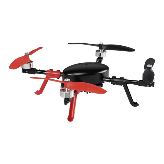
Page 14: Your Xtreme
10. YOUR XTREME 14 | Your Xtreme... - Page 15 Xtreme Rear propeller (Black) 11 Adhesive-backed hook and loop Rotor strap Canopy 12 Battery tray Mode 1 Spinner 13 BIND button 14 Battery connection socket Front propeller (Red) 15 Flight battery Orientation LED 16 4-pin battery plug Boom 17 Charger socket 5a 4a Status LED 18 USB LiPo charger 10 PPM cable (here shown installed) Transmitter – Mode 1 1a HEIGHT HOLD button 6a ON/OFF button 2a Right control lever...
-
Page 16: Dimensions
11. DIMENSIONS Standard Xtreme Aerial Kit – 89064RC (not included) 6.4˝ (~162.6 mm) 9˝ (~228.6 mm) 6.4˝ (~162.6 mm) 6.3˝ (~160 mm) 9˝ (~228.6 mm) 0.59˝ (~15 mm) 5.43˝ (~138 mm) 6.3˝ (~160 mm) 2˝ (~50.8 mm) 5.91˝ (~150 mm) 16 | Dimensions... -
Page 17: Weights And Payload
12. WEIGHTS AND PAYLOAD 13. DIRECTIONS This is an important section to read. If you do not follow 13.1 Front and back the instructions, the »Xtreme may not take off or even be damaged. Front and back of the »Xtreme are indicated by colour. The RED PROPELLERS LEGS point to the front of the »Xtreme. The BLACK PROPELLERS and LEGS point to the rear of the »Xtreme. -
Page 18: Quick Start Aviation Terms
14. QUICK START AVIATION TERMS 14.4 Hover HOVER denotes a flight status in which the »Xtreme neither rises nor falls so that the upwards directed uplift force is equal to the downwards directed weight. 14.1 Rudder 14.5 Altitude height hold > RUDDER denotes the rotation of the »Xtreme around the rudder axis (vertical axis). This movement either occurs unintentionally due to the speed torque of the propellers > ALTITUDE HEIGHT HOLD is a product feature of the »Xtreme. Altitude height hold or intentionally as a flight direction change. -
Page 19: Battery
LiPo chargers. Only use the included USB charger or other battery from RC Logger. suitable RC Logger chargers to charge the flight battery. After the flight, the LiPo flight battery must be disconnected Use a suitable plug-in mains adapter or a cigarette lighter from the »Xtreme. -
Page 20: Insert Batteries Into Transmitter
15.3 Insert batteries into transmitter > Individual battery cells of a battery pack are usually different. The USB charger has two separate chargers integrated. Therefore, it is possible that a battery cell is already charged (LED off) and the other battery cell is still being charged (LED on). (6b) of the transmitter by pushing its Remove the lid of the battery compartment (5a) lever slightly down and lifting the lid off. Wait until both LEDs have gone out before unplugging the 2. Insert two micro/AAA size batteries into the battery recessions. Observe the correct battery. polarity when inserting. Polarity indications are provided inside the compartment. 3. Replace the battery compartment lid again. Ensure proper locking of the lid lever. Since the transmitter requires very little power, batteries will keep much longer. We recommend the use of high- quality alkaline batteries. -
Page 21: Attaching The Flight Battery
15.4 Attaching the flight battery Before you connect the battery to the »Xtreme turn on the transmitter. An unbound (transmitter and »Xtreme cannot communicate) aircraft is considered uncontrolled. 1. Carefully turn the »Xtreme upside down and place it on a stable and soft surface. 2. Sufficiently support the »Xtreme from below. Plug the 4-pin battery plug (16) into the battery connection socket (14) at the under- side of the »Xtreme. You can only connect the plug in one direction. Do not force the plug into the socket to avoid damage to the connectors. -
Page 22: Transmitter
> If you move the ELEVATOR/RUDDER lever (9a) to the left, the »Xtreme will turn to the left. If you move ELEVATOR/RUDDER lever to the right, the »Xtreme will turn 16.1 RC Logger transmitter to the right. > Please note that no stock transmitter is supplied with model 88009RC (ArF). > If the »Xtreme rotates slowly around its own axis in hover flight, trim it with the trim buttons. Push the corresponding trim buttons until the »Xtreme no longer rotates 16.1.1 Mode 1... - Page 23 Trimming Fig. 5 Fig. 3 Trimming Trimming Fig. 4 Fig. 6 Transmitter | 23...
-
Page 24: Mode 2
16.1.2 Mode 2 16.1.2.3 Elevator > See [ Fig. 9 > This section introduces the MODE 2 transmitter. Carefully read the following sections to aquire a good understanding of the transmitter’s functionality. > If you move the AILERON/ELEVATOR lever (2b) to the front, the »Xtreme will move forwards. If you move the AILERON/ELEVATOR lever to the rear, the »Xtreme will > Some aviaton terms are used in this section. Please also refer to chapter “14. Quick move backwards. start aviation Terms” on page 18. - Page 25 Trimming Fig. 7 Fig. 9 Trimming Trimming Fig. 8 Fig. 10 Transmitter | 25...
-
Page 26: Binding
5. Press and hold the ON/OFF button until you hear a beep sound every 3 seconds. You are now in binding mode. Release the button. When using the RC Logger OneLINK, turn off signal 6. Wait until the »Xtreme’s status LED flashes in the corresponding color related to transmission via antenna on your transmitter. Signal the selected flight mode indicating that the binding process has been completed. -
Page 27: Preparation
16.3.1 Preparation 16.3.2 Mounting the OneLINK to your transmitter In order to make use of the “OneLINK” option you will need to prepare the following items: The best and easiest application is to use some adhesive-backed hook and loop fastener. The “OneLINK” can then be removed when not needed. Apply a small amount of either > Your own transmitter with: [ Fig. 11 hook or loop to the back of your transmitter and the “OneLINK”. See » Min. 6 channels (7 channels are recommended) 16.3.3 Preparing your OneLINK for Spektrum transmitters »... -
Page 28: Important Notes In Regards To Learning The Onelink
4. Connect interface cable 16.3.5 Learning the OneLINK > Connect the interface cable (for this case: microUSB / 3.5 mm stereo jack) from the For your own safety, remove the propellers before you transmitter to the “OneLINK”. Power on the “OneLINK” via the top most button (Short start the learning procedure. After the test, following the press). learning procedure, is passed sucessfully you may mount > Refer to the supplied user instructions if necessary. the propellers again. -
Page 29: Binding The Onelink To The »Xtreme
3. Learn throttle (Channel-1) If no input is detected from Channel-7 (approx. 5 seconds), > Move THROTTLE up and back down again (full up to full down). learning will be completed automatically and the final 2 > The LED will blink red 2 times indicating Channel-2 learning. position switch (AUX-3) is ignored! (Applicable for DX6i) 4. -
Page 30: Verify Learning
3. Press and hold the bind button located next to the battery connector of the »Xtreme for Test 4 - Acrobatic/Normal/Height hold 2 to 3 seconds. Wait until the status LED starts flashing red and green. The »Xtreme is now in bind mode. Test 4 must be performed in SPORT mode! 4. Press and hold the middle button on the “OneLINK”. An audible signal will be emitted. The status LED on the »Xtreme will start flashing (green, orange, or red) depending on To turn off altitude height hold mode toggle the second what flight mode is enabled on the transmitter. - Page 31 16.3.8.2 Gear channel 2. Scroll to “Flap-land” » adjust to “100”. Carefully observe the direction of the arrow. [ Fig. 14 The following setup will enable DX6i users to toggle from SPORT to EXPERT MODE 3. Exit the “Flap” menu » scroll » enter “Setup list”. Scroll and enter “Reverse”. using the GEAR CHANNEL on the transmitter (These modes have been selected as it will be the most commonly used by pilots using their own transmitter). You will now need to reverse the “Flap” channel. See [ Fig. 15 4. Exit the “Setup list” menu. 1.
- Page 32 16.3.8.4 Learning procedure DX6i 5. Learn elevator (Channel-3) > Move ELEVATOR up and back to centre again. 1. Prepare > The LED will blink red 4 times indicating Channel-4 learning. Turn on the “OneLINK”, and ensure it is connected to the trainer port of your DX6i. Before starting the learning procedure, position all switches to their “0” position and move the 6.
-
Page 33: Ppm Mode
16.4 PPM Mode > A true PPM receiver supporting a minimum of 6 channels (7 CH system recommended). PWM receivers are not suitable and will not work. > A receiver connection cable that connects your PPM receiver with the PPM socket of 16.4.1 Introduction the »Xtreme (included in delivery). The »Xtreme provides the option to allow users to install a PPM RECEIVER in order to The following sections will guide you through the installation process and set-up. Do not control the »Xtreme with a standard RC transmitter instead of the default stock transmitter. skip any sections as they are interdependent. -
Page 34: Connecting And Mounting The Ppm Receiver
3. Assign the transmitter channels as following: » Channel 1: AILERON » Channel 2: ELEVATOR » Channel 3: THROTTLE » Channel 4: RUDDER » Channel 5: A UX-1 { FLIGHT MODE selector (Beginner, Sport, Expert), 3-way toggle switch } » Channel 6: A UX-2 (ACROBATIC mode, NORMAL flight, ALTITUDE HEIGHT HOLD mode, 3-way toggle switch) »... -
Page 35: Binding
» W: White » B: Black » R: Red 2. Route the PPM cable through the lower flight control circuit board and main frame towards the front orientation LED. » To best route the wire, make use of the gap near the motor wire socket as shown [ Fig. -
Page 36: Learning Procedure
16.4.6 Learning procedure 5. Learn rudder (Channel-2) > Move RUDDER to the left and back to centre again. For your own safety, remove the propellers before you > The LED will blink red 3 times indicating Channel-3 learning. start the learning procedure. After the test, following the 6. -
Page 37: Verify Learning
16.4.6.11 Notes 2. Test 2 - Orientation LEDs > Move AILERON stick right with ELEVATOR down (bottom right corner). Mode Channel Switch Function > The orientation LEDs turn on or off depending on their state. Repeat the steps to switch AUX-1 Channel 5 Position 1: BEGINNER MODE their states. -
Page 38: Futaba ® Transmitters Without 3-Way-Toggle-Switch
16.4.8 Futaba transmitters without 3-way-toggle-switch » By default you will toggle between ACROBATIC and NORMAL flight or, after ® shifting the end points, between NORMAL and ALTITUDE mode. 16.4.8.1 Workaround solution IMPORTANT! Channel 5 (CH 5) must include SPORT mode. Channel 6 (CH 6) must include NORMAL FLIGHT. In case you do not have a free 3-way toggle switch available on your transmitter, you may assign a 2-way-toggle-switch instead and shift your channel END POINT after performing [ Fig. -
Page 39: Using A Camera
17. USING A CAMERA 17.2.1.3 Propellers > The standard propellers do not provide enough lift to carry a camera. Therefore, a set of larger propellers help increase lift, which in turn allow for a larger payload. > For instructions on how to replace propellers, refer to section “19.3.1 Replacing 17.1 Introduction propellers” on page 53. You have the possibility to attach a camera to the »Xtreme by using the “RC Logger A erial Kit” 17.2.2 Attaching the camera tray (89064RC). The “Aerial Kit” is not supplied with the »Xtreme. However, it is described here > The camera tray can be mounted without any further modification on the »Xtreme. in detail as it is a necessary accessory when intending to attach a camera to the »Xtreme. -
Page 40: Replacing Propellers
Fig. 22 17.2.4 Replacing propellers 17.2.4.2 Replacement process > To replace the propellers follow the instructions provided in section “19.3.1 Replacing 17.2.4.1 Direction propellers” on page 53. > Use the larger propellers supplied with the “Aerial Kit” instead of replacement propellers. Mind the colour coding and ”R” and ”L” markings of the propellers. > Note that the RED PROPELLERS indicate front. The BLACK PROPELLERS indicate rear. When replacing the propellers do not mix them up. > There is one more property to consider when replacing the propellers. Propellers are marked with ”L”... -
Page 41: Attaching The Camera
17.3 Attaching the camera 17.3.1 Clearance Make sure the camera is not taller than the AVAILABLE CLEARANCE between camera tray and ground. The »Xtreme must always stand on its own legs for takeoff and landing. 17.3.2 Action mounts There are suitable action mounts available from www.rclogger.com. These action mounts can be directly mounted on the cameray tray and are compatible with some RC Logger action cameras. 17.3.3 Double-sided tape >... -
Page 42: Flying The Xtreme
18. FLYING THE XTREME Alarm III: 6 min 3 x beep [3 sec pause], 3 x beep [3 sec pause], 3 x beep [3 sec pause], 3 x beep Alarm IV: 7 min 4 x beep [3 sec pause], 4 x beep [3 sec pause], 4 x beep [3 sec pause], 4 x beep 18.1 Built-in safety 18.1.3 Xtreme 18.1.1 General > The STATUS LED flashes: » Flashes slowly if transmitter is bound and signal strength is sufficient. The »Xtreme has a range of SAFETY FEATURES in the transmitter and model which protect the model from damage and/or should reduce possible damage to a minimum. -
Page 43: Accident Prevention
18.2 Accident prevention 18.2.4 Area clearance Do not fly the »Xtreme in the vicinity of people and animals. Keep a clearance area of at least 10 x 10 m. 18.2.1 General advice The »Xtreme is a professional toy. Professional in this respect means having sufficient 18.2.5 Learn from experienced pilots knowledge of its functions and the awareness of the possible dangers involved. Careless We consider it helpful that you consult a model craft flight trainer or an experienced model operation can cause serious damage and injury. Fly the »Xtreme with necessary caution craft helicopter pilot to provide you the necessary guidance to get started with the »Xtreme. -
Page 44: First Steps
18.3 First steps 18.4.2 Beginner mode > The BEGINNER MODE is specifically designed for users who are new to flying multi- rotor systems. The control respond is slow and may feel “slaggy” to some extend. 18.3.1 Turn transmitter on and off This behavior is intentional, allowing pilots to get a first feeling as to how the »Xtreme The use of the supplied stock transmitter is described here. For your own transmitter refer responds to lever commands. to its operating instructions and your own configuration respectively. > AUTO-LEVELLING is enabled in beginner mode, thus if the pilot lets go the aileron >... -
Page 45: Expert Mode
18.5 Your first flight > Before moving on to EXPERT MODE, fully gain confidence in sport mode first. Do not progress too fast, be patient and disciplined before you move on to the next mode, to avoid crash and disappointment. 18.5.1 General information > A brief summary of the sport mode: > The »Xtreme is essentially equipped with the handling of a normal helicopter. The » Sport mode is not designed for confined indoor flying. differences, however, are in the detail. For helicopters, the torque balance is stabilised »... - Page 46 Mode 1 Mode 1 Fig. 24 Fig. 26 Mode 1 Mode 1 Mode 2 Mode 1 Mode 1 Mode 2 Fig. 25 Fig. 27 46 | Flying The Xtreme...
-
Page 47: Gyro Reset
18.5.3 Gyro reset 18.5.5.2 Mode 2 1. Start the motors by carefully moving the THROTTLE/RUDDER lever diagonally into It is good practice to reset the gyros before every flight by the left bottom corner (see [ Fig. 27 ]). Hold this position until the motors turn on. following section ”19.2 Resetting flight leveling gyro” on 2. It may be necessary to slighty move the lever until you find the correct position. page 51. 3. -
Page 48: Landing
18.5.8 Landing Be careful when applying RUDDER, which will rotate the > To land the »Xtreme again, decrease the THROTTLE slightly until the »Xtreme »Xtreme around its vertical centre axis, causing you to gravitates to the ground. A somewhat solid touchdown on the ground is no problem and become disoriented. -
Page 49: Preparation
18.6.4 Flip and roll Product warranty does not include replacement of The use of the supplied stock transmitter is described here. For your own transmitter refer parts, compensation for property damage of any kind, to its operating instructions and your own configuration respectively. compensation for personal injury or injury to others resulting from any flight manoeuver where recommended > You FLIP by activating the acrobatic flight mode and move ELEVATOR to any safety guidelines have not been followed by the pilot. -
Page 50: Altitude Height Hold Function
18.7 Altitude height hold function 18.6.5.2 EXPERT mode flip recommendation 1. Accelerate the »Xtreme upwards by pushing throttle to maximum. 18.7.1 Introduction 2. Start flip by pushing AILERON (Roll) or ELEVATOR (Flip) to any maximum direction and reduce throttle to approx 25%. The ALTITUDE HEIGHT HOLD function lets you hold the »Xtreme in a set flight altitude. 3. As soon as the »Xtreme is back in upright position increase THROTTLE to help the copter stabilise again. The status LED + orientation LEDs flash fast while the 4. -
Page 51: Maintenance, Care And Repair
19. MAINTENANCE, CARE AND REPAIR 19.2 Resetting flight leveling gyro 19.2.1 General 19.1 Regular cleaning and maintenance > In case your »Xtreme appears to be drifting in one direction, noticeable especially in beginner mode, you may need to reset the sensor calibration. > If you need to continuously trim the »Xtreme to ensure proper flying then this may be 19.1.1 Cleaning due to the following reasons: The »Xtreme is a simple but well-designed flying device. There are no mechanical parts » A motor shaft might be slightly bent or a propeller is defective resulting in that need to be lubricated or require special maintenance. However, after each flight vibrations. Either replacing the motor(s) or installing a complete new set of operation you should clean the »Xtreme of possible dirt (wool strings, dust, etc.). -
Page 52: Mode 1
19.2.2 Mode 1 The use of the supplied stock transmitter is described here. For your own transmitter refer to its user instructions and your own configuration respectively. Mode 1 1. Place the »Xtreme onto an as flat as possible level surface. 2. Power on the transmitter and connect the flight battery. 3. Move the THROTTLE/AILERON lever diagonally into the right bottom position, and [ Fig. 28 move the ELEVATOR/RUDDER lever fully up vertically. See 4. Hold the levers at their positions until the transmitter emits an ACOUSTIC SIGNAL and the »Xtreme’s STATUS LED TURNS SOLID GREEN. 5. -
Page 53: After A Crash
19.3 After a crash 19.3.1.1 Inspection > If a propeller is damaged in a crash or other action, replace it immediately. It is strongly suggested to always inspect for damage. > This also applies if there are any fine tears or grazing in the propeller. Due to the high Replace defective parts immediately. Defective parts can speed, material parts could come loose if the propellers are damaged and this could impact properly working parts! lead to damage to or endangerment of the environment. -
Page 54: Replacing Motor
19.3.1.3 Replacement > See [ Fig. 31 1. Loosen the spinner counter-clockwise and remove it. 2. Remove the washer and pull the propeller off the motor shaft. 3. Slide a new propeller (mind the direction: “L” or “R”) onto the motor shaft. The propeller only fits in one direction. You may need to turn it slightly to find the correct position. 4. Install a new washer. 5. Replace the spinner and tighten it with moderate force. Overtightening leads to damage of the motor shaft thread and propeller. -
Page 55: Disposal
20. DISPOSAL 21. FCC COMPLIANCE STATEMENT FCC ID: OMO-M-19 20.1 General Statement according to FCC part 15.19 This device complies with Part 15 of the FCC Rules. Operation is subject to the following In order to preserve, protect and improve the quality of environment, protect two conditions: human health and utilise natural resources prudently and rationally, the user > This device may not cause harmful interference, and should return unserviceable product to relevant facilities in accordance with statutory regulations. The crossed-out wheeled bin indicates the product needs > This device must accept any interference received, including interference that may to be disposed separately and not as municipal waste. -
Page 56: Technical Data
23. TECHNICAL DATA 23.2 Remote control Supply voltage ........3 V/DC (2 x AAA batteries) Transmission frequency.....2.4 GHz 23.1 Xtreme Number of channels ......Auto selection by frequency hopping (FHSS) Power supply ........7.4 V LiPo rechargeable battery Transmitter range ......max. 400 ft (~122 m), open field Operating temperature ......+32 to 104 °F (0 to +40 °C) Dimensions (W x H x D) ....5.91 x 3.94 x 2.76″ (~150 x ~100 x ~70 mm) Operating humidity ......max. 75 % RH, non-condensing Weight ..........4.59 oz (~130 g) Operation environment ......Indoor and outdoor (dry weather conditions) 23.3 Charger Wind conditions .........Zero to light wind Diameter without propellers ....7.09″ (~180 mm) Supply voltage ........5 V/DC Propeller diameter ...... 5 .43″ (~138 mm), Standard... -
Page 57: Declaration Of Conformity
24. DECLARATION OF CONFORMITY 25. LEGAL NOTES Manufacturer: CEI Conrad Electronic International (HK) Limited These operating instructions are published by CEI Conrad Electronic International (HK) Limited, 18th Floor, Tower 2, Nina Tower, No. 8 Yeung Uk Road, Tsuen Wan, New License holder: CEI Conrad Electronic International (HK) Limited Territories, Hong Kong. Address: 18th Floor, Tower 2, All rights including translation reserved. Reproduction by any method, e.g. photocopy, Nina Tower, No. 8 Yeung Uk Road, microfilming, or the capture in electronic data processing systems require the prior written Tsuen Wan, New Territories, Hong Kong... - Page 60 www.rclogger.com...
Need help?
Do you have a question about the Xtreme 88007RC and is the answer not in the manual?
Questions and answers