
Related Manuals for Data Connect IG202T

Summary of Contents for Data Connect IG202T
- Page 1 DATA CONNECT ENTERPRISE User’s Manual IG202T and IGV23 Modem Document Number 520-01005-001 Rev. A...
-
Page 2: Table Of Contents
DATA CONNECT Contents Contents ........................iii Figures........................iv Chapter 1 Introduction .................... 5 Features ........................6 Applications ......................... 7 Chapter 2 Installation ....................8 Unpacking Your Hardware ..................8 Additional Items You Need to Complete Your Installation........... 8 Hardware Overview..................... 9 Front View ........................ -
Page 3: Figures
Figures Figure 1-1. Point-to-Point Network Using the IG202T/V23 Modem ........7 Figure 1-2. Multipoint Polling Network Using the IG202T/V23 Modem ........7 Figure 2-1. Front View of the IG202T/V23 Modem ..............9 Figure 2-2. Back View of IG202T Modem ................10 Figure 2-3. -
Page 4: Chapter 1 Introduction
IG202T, a Bell 202 compatible, and the standalone IGV23, an ITU-V23 compatible modems. The Data Connect IG202T/V23 modem is a 0 to1200 bps modem designed for 4- wire, full-duplex or 2-wire, half-duplex operation over a voice-band leased line or private line. -
Page 5: Features
The IG202T/V23 modem is specifically designed for harsh environments typically associated in utility substations and industrial facilities. Though functionally similar to commercial modems, the IG202T/V23 provides the following unique features that make it well suited for utility and industrial applications. -
Page 6: Applications
Introduction Applications The IG202T/V23 modem is designed for point-to-point and multipoint data communications. Figure 1-1 shows a typical point-to-point configuration using the IG202T modem and Figure 1-2 shows a typical multipoint configuration using the IG202T modem. Modem Modem Remote Terminal Workstation Figure 1-1. -
Page 7: Chapter 2 Installation
Your package should include: At least one of the following IG202T or IGV23 modems: – Model IG202T or IGV23 for 90 to 265 VAC or 100 to 400 VDC – Model IG202T-DC or IGV23-DC for 10 to 60 VDC –... -
Page 8: Hardware Overview
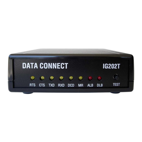
A loopback control push-button switch (see Loopback Control Switch on page 21) Figure 2-1. Front View of the IG202T/V23 Modem Back View Figure 2-2 shows the back view of the IG202T stand-alone modem. Starting from the left side, this view shows: A 4-wire/2-wire configuration block labeled LEASED LINE... -
Page 9: Rack-Mount View
Figure 2-2. Back View of IG202T Modem Rack-Mount View Figure 2-3 shows the rack-mount plug-in module. Figure 2-3. Rack-Mount Module for the IG202T-RM Modem Board Installation Summary This section describes the steps for installing the modem. User’s Manual - SM202T/SMV23 Modem... -
Page 10: Configuring The Modem
Installation NOTE: It is important to follow the steps below to configure the modem’s DIP switches to match your DTE/RTU interface requirement and the transmission line characteristics. If you are not certain about your system’s parameters or the leased-line configuration, please contact your network administrator for assistance. -
Page 11: Figure 2-4. Ig202T & Igv23 Stand-Alone Modem Board
Installation 3. Replace the top cover after the configuration is completed. Configuration Switch Configuration Jumpers (SW1) JP1 & JP2 Figure 2-4. IG202T & IGV23 Stand-alone Modem Board User’s Manual - SM202T/SMV23 Modem... -
Page 12: Setting The Dip Switches
Receiver Termination High-Z 600 ohm Figure 2-5. IG202T & IGV23 -mount Modem Board Setting the DIP Switches SW1 is a 8-position DIP switches used to configure all the options and features of the modem. Table 2-3 shows the setting of the switches. -
Page 13: Sw1-1 Auto Rts
Installation SW1-1 Auto RTS SW1-1 ON = Enable Auto RTS SW1-1 OFF = Disable Auto RTS (default) For data terminals that do not provide hardware Request To Send (RTS), set switch SW1-1 to ON to enable auto RTS mode. In this mode, TXD is detected at the modem and an internal RTS signal is turned ON. -
Page 14: Sw1-4 - Soft Carrier Control
Installation SW1-4 – Soft Carrier Control SW1-4 ON = Soft Carrier is enabled SW1-4 OFF = Soft Carrier is disabled In Bell 202T mode, when soft carrier mode is enabled, a carrier frequency of 900 Hz is transmitted at the end of a transmission in order to turn off the carrier detect (CD) at the receiving modem. -
Page 15: Sw1-8 Receiver Termination Impedance
Installation This configuration should be used for all slave modems to prevent the transmitting modem from being unnecessarily burdened. To select this configuration, set switch S1-7 ON for the slave modems. If you use the modem with transmission lines that are transformer-coupled or with an impedance-isolated network (such as a transformer bridge), set switch S1-7 OFF for proper operation. -
Page 16: Jp2 Rs-232 Or Rs-485 Serial Interface (Standalone Only)
Installation RS-232 or RS-485 Serial Interface (Standalone Only) JP2, a 6-pin header, is used to select the communication port for the modem. You may select to use either the RS-232 or RS-485 port. Only one type of interface is supported by the modem. -
Page 17: Connecting To A Transmission Line
Installation Connecting to a Transmission Line The modem has a transmission line interface (RS-11C) that can be configured for 2- or 4- wire analog connection, where in 4- wire connection, one pair (Tx-A and Tx-B) is used to transmit data and the other pair (Rx-A and Rx-B) is used to receive data. The transmit pair and receive pair are non-polarized. -
Page 18: Connecting To A Voltage Source
Model IG202T (with AC-DC power converter): 90 to 265 Volts AC, 50 to 60 Hz, single phase or 100 to 400 VDC. The output of the converter is a 12 VDC source that will power the modem. -
Page 19: Connecting To An Rs-232 Device
Installation Connecting to an RS-232 Device The modem back panel provides a female, 9-pin RS-232 connector that accepts an attached RS-232 device (see Figure 2-2 on page 10). This connector accepts a standard connection to a DTE (RTU) that conforms to the pin assignments shown under “RS-232 (DTE) Interface”... -
Page 20: Leds
Installation LEDs The front panel of the modem provides the LEDs shown in Table 2-3. Table 2-4. Modem LEDs Color Description Yellow Request To Send Yellow Clear To Send Yellow Transmit Data Yellow Receive Data Yellow Carrier Detect Yellow Modem Ready Red* Local Analog Loopback Red*... -
Page 21: Figure 2-8. Loopback Diagnostic Modes
Installation Figure 2-7 shows these three loopback diagnostics. Transmitter Receiver Leased Line HOST Transmitter Receiver Local (Host) Analog Loop Back Transmitter Receiver Leased Line HOST Receiver Transmitter Local (Host) Digital Loop Back Transmitter Receiver Leased Line HOST Receiver Transmitter Remote (RTU) Digital Loop Back Figure 2-7. -
Page 22: Problem Solving
DATA CONNECT ENTERPRISE Appendix A Troubleshooting In the event you encounter a problem using your Data Connect Enterprise modem, refer to the troubleshooting information in this appendix. IMPORTANT: If you encounter a problem with your modem, be sure the switches on the modem are set to the appropriate positions (see Table 2-1 on page 13). -
Page 23: General Specifications
Operating temperature: -40 C to +85 C Power supply: Wide range switching power supply: IG202T (AC version): 90 to 265 Volts AC, 50/60 Hz, single phase or 90 to 400 VDC IG202T-DC (DC version):10 to 60 Volts DC Surge protection:... -
Page 24: Figure 2-9. Back-To-Back Connection To A Second Modem
Specifications Weight: 0.5 lbs without AC to DC power converter module Interface connectors Leased Line: 4-position RJ-11C modular Jack Data Terminal Equipment: DB-9 female connector (for RS-232) RJ-11C module jack (for RS-485) Interface Connector Pin Assignments Table B-1. Leased Line RJ-11C Pin Assignments This Pin Number…... -
Page 25: Environmental Specifications
Specifications RS-232 (DTE) Interface Table B-2. RS-232 (DTE) Interface Signal Name Modem Input/Output DB-9 Pin Description Output Data Carrier Detected Output Receive Data Input Transmit Data Signal Ground Output Data Set Ready (Modem Ready) Input Request To Send Output Clear To Send RS-485 (DTE) Interface Table B-3.
Need help?
Do you have a question about the IG202T and is the answer not in the manual?
Questions and answers