
Summary of Contents for energy sentry 9212 Series 3
- Page 1 Computerized Energy Management Model 9212 Series 3 Owner’s/Installation Manual Helping you to use energy more effi ciently...
-
Page 2: Table Of Contents
Table of Contents Operating Instructions Notice to Users ..........................1 Introduction and Overview of Demand Control ................. 2 Superior Features of the 9212 ......................4 System Description ........................5 System Operation ........................... 6 Control Panel Settings & Displays ..................6 Basic Operations ......................... -
Page 3: Notice To Users
FAX (970) 461-9605 www.brayden.com WARNING: The installation of the Energy Sentry® Demand Controller is required to be done by a duly licensed and qualified electrician or electrical contractor. Notice to Users This equipment generates and uses radio frequency energy and if not installed and used properly, that is, in strict accordance with the manufacturer’s instructions, it may cause interference to radio and television reception. -
Page 4: Operating Instructions
Congratulations on your decision to purchase the Billing under the demand rate works like this: Suppose Energy Sentry Model 9212 Series 3 Electric Demand you are heating or cooling your home, washing dishes, Controller. As the owner of an all-electric home metered... - Page 5 To benefit from your Energy Sentry 9212 Demand Con- peak demand. This is illustrated by Owner B in Figure 1. troller you must have a demand measuring electric meter...
-
Page 6: Superior Features Of The 9212
Demand Rate. The energy usage is 3000 Kwh of the 9212 which is the same as in Case I and Case II. The difference is that an Energy Sentry 9212 is now installed and peak B u d g e t i n g a n d E n e r g y demand is reduced to a maximum of 8 KW. -
Page 7: System Description
System Description EEPROM Non-Volatile Memory for Maximum Your Energy Sentry 9212 Electrical Demand Controller Flexibility consists of three basic components: these include the Energy Sentry’s EEPROM memory “remembers” all Control/Display Unit, the Relay Unit and the Current system settings you have entered even when power is Transformers. -
Page 8: System Operation
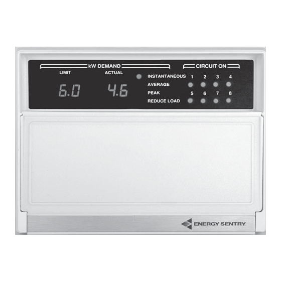
Figure 2. 9212 Control/Display Unit System Operation Relay Unit The Relay Unit, normally mounted near the load center, Control Panel Settings & contains up to eight power relays, capable of switching 16 electrical circuits, which turn the loads controlled by Displays the 9212 on and off. -
Page 9: Basic Operations
A Circuits On labeled “9212 Energy Sentry Demand Controller” or indication does not necessarily mean that the controlled similar. If this breaker is off, it should be turned on. If load is on, but rather the load is free to go on if the you cannot locate a breaker labeled “9212,”... - Page 10 Simultaneously press the Decrease Key (8) Step 4, Reset Peak: This step is optional depending or the Increase Key (9) until the desired upon the time interval for which a record of your highest demand limit is reached. The numbers in average (peak) is desired.
- Page 11 Installation section of this manual for detailed instruc- ing the limit further. It may take as long as one hour for tions or contact your Energy Sentry dealer. the new level to be reached. L L L L L oad Shedd ing Sequence...
- Page 12 Control of Clothes Dryer Turn on oven and all top elements of your stove. Make sure that the instantaneous demand display The clothes dryer is usually one of the last circuits that mode shows the demand at least 6 KW or higher the 9212 Load Controller sheds.
- Page 13 The Energy Sentry 9212 Controller simply acts as an- with your utility company. You can check past bills to other switch on the water heater, dryer or heating/ determine this date or call the utility directly.
-
Page 14: If You Need Service
If You Need Service Your Energy Sentry Model 9212 has been carefully assembled and tested at the factory in Loveland, Colo- rado, USA. Only components having high reliability and long life have been used in its manufacture. In the event that a failure does occur, your 9212 has been designed so household appliances and loads will con- tinue to function. -
Page 15: Appendix A
As this limit is approached, the demand controller. As the demand approaches the Energy Sentry Controller begins shutting off pre- demand limit, the demand controller uses the priority determined loads to control peak demand. -
Page 16: 1.0 Introduction
Note: All wiring must be installed in accordance FG9841A 9212 Control/Display with national and local electrical codes. Unit Important: If the Energy Sentry 9212 is to be con- Current Transformer – nected to a heat pump compressor or air conditioning 8420-3028 One pair of two types: compressor, ensure that you complete Section 17, “Sys-... -
Page 17: Locating The Control Unit
LOAD RELAY UNIT LOAD CENTER 3.2 System Overview The Energy Sentry 9212 Demand Controller System consists of three general pieces: the Control/Display Figure 4. Locating and Mounting the Control Unit (C/D) Unit, the Relay Unit and the Current Transformers. Figure 1 shows the General System Configuration. The C/D Unit mounts inside the home, usually in a general living area such as the kitchen, entry way or family room. -
Page 18: Locating And Mounting The Relay Unit
5.1.2 Rain Tight Relay Unit Use the Control/Display Unit mounting template (en- (P/N FG9212A-XXXRXXX) “RT” closed) to locate and mark the hole cutout and screw This relay unit is provided with a 12" x 10" x 4" (or locations or see Figure 4. Be careful to locate the hole larger) NEMA 3R Raintight Enclosure. -
Page 19: Wiring The Control Cable To C/D Unit
Figure 5. Wiring the Control Cable 9212 CONNECTIONS GREEN CDC3 9841A CONTROL/ DISPLAY CDC4 UNIT No Connect WHITE BLACK CLASS 2 OUTPUTS OUT 2 A/C #1 9202 OUT 3 A/C #2 DATA/LINK BOARD CLASS 2 RELAY OUTPUTS RELAY UNIT 7.0 Wiring the Control Cable Control/ Pass the four wires of the control cable through the... -
Page 20: Mounting The C/D Unit
Install a single pole 120 volt 15 amp circuit breaker in the screws provided (P/N 2520-1001), use a Phillips head breaker panel for the Energy Sentry and mark it “Energy screwdriver to insert the screw through the plastic hous- Sentry Demand Controller.”... -
Page 21: Installing And Wiring Current Transformers
11.3 vided in Section 17 of this manual or may also be obtained from the factory or from your Energy Sentry Run current transformer leads into relay unit via the conduit representative. if current transformers are installed within breaker panel and... -
Page 22: Wiring The Power Relays To Heat Circuits And Hot Water Heater
Schedules may be altered as necessary to suit the needs of 13.3 the particular home and user. This is an example only. For applications assistance, contact your Energy Sentry The relay is inserted in series with the load on one side representative. -
Page 23: Wiring The Power Relays To Dryer
This schedule may be altered as necessary to suit the needs of the particular home and user. This is an example only. Your situation may be different. For assistance contact your Energy Sentry representative. Circuits with compres- sors must have minimum off and minimum on times programmed in. See Section 17 for system programming procedure. -
Page 24: Wiring The Power Relays To Heat Pumps And Air Conditioners
BREAKER 15.2 Connecting air conditioners and/or heat pump compres- sors to the Energy Sentry unit is normally accomplished TEST: DRYER STARTS WITH RELAY OPEN by inserting a relay in series with the low voltage 24 VAC thermostat control loop as shown in Figure 10 14.4... -
Page 25: 16.0 System Checkout
All relays will open approximately one-half second after power is restored. If problems still arise, 16.0 System Checkout call your Energy Sentry representative. 16.2.3 16.1 Prior to Test All eight “Circuits On” indicator lights should be off after power up. -
Page 26: System Programming
16.4.1 “down” keys. Insure all controlled load breakers in the load center are The six groups of questions are as follows: off except for the 15 Amp “Energy Sentry Demand Group # Function # of Questions Controller” breaker. Observe the Instantaneous De-... - Page 27 to change the priority of Circuit #2 press Step 2. An "oL" will appear in the left window. the Increase or Decrease Key until the This is the off-peak demand limit setting desired priority is displayed in the Actual which is essential when your 9212 is display window.
- Page 28 9212. If you need additional Step 21. Repeat Step 20 for Circuit #2 Minimum information or assistance in programming the Off Time. 9212, contact your Energy Sentry represen- tative. Step 22. Repeat Step 20 for Circuit #3 Minimum Off Time.
- Page 29 17.2 Examples of 17.2.2 17.2.2 17.2.2 17.2.2 17.2.2 Programs For the load schedule shown in Section 12.1.2, the 17.2.1 17.2.1 17.2.1 17.2.1 17.2.1 following system program is recommended: For the load schedule shown in Section 12.1.1 the System Program 2 following system program is recommended: Selected Load Control Strategy: Fixed Priority.
- Page 30 fixed sequence. Hot water heater (#3) and dryer (#1) System Program 4 connected to unit, 2 circuits. Heat pump compressor connected to unit on circuit #2. Selected Load Control Strategy: Rotate/Fixed Priority Electrical Service Size: 80 KW. System Configuration: Eight relays installed Demand Averaging Period: 60 minutes.
-
Page 31: Wrap-Up
18.4 Relays in relay unit should be turning loads on and off as necessary. 18.5 Replace the cover on the Energy Sentry and on the breaker panel. 18.6 Turn to the back page of this manual. Record the following information in the spaces provided: •... - Page 32 Energy Sentry Controller or its compo- the unit which is located on the inside of the nents that proves to be defective, provided that you relay unit.
-
Page 33: Warranty Information
Required Warranty Information Installing Electrician: Fill out applicable information on this page & items 5, 6, 7 and 8 on warranty card. Strategy Load Schedule and Control (check applicable strategy): Fixed Rotating Combination Fixed/Rotate Control Household Circuit Priority Minimum “On/Off” Circuit Assignment/Description (if applicable) - Page 34 Brayden Automation Corp. 6230 Aviation Cicrle Loveland, CO 80538 (970) 461-9600 FAX (970) 461-9605 www.brayden.com P/N 09212-94100E...
Need help?
Do you have a question about the 9212 Series 3 and is the answer not in the manual?
Questions and answers