Table of Contents
Advertisement
Advertisement
Table of Contents

Subscribe to Our Youtube Channel
Summary of Contents for QTX Light DM-X16
- Page 1 DM-X16 192 Channel DMX Controller USER MANUAL 154. 093UK Vers ion 1.0...
-
Page 2: Table Of Contents
DMX 512 CONTROLLER SERIES Contents Contents Before you begin What are included..................Unpacking instructions ................Safety instructions ..................Installation Features ....................General overview ..................Product overview (front) ................Product overview (rear panel) ..............Common terms ................... Operating instructions 3.1 SETUP 3.1.1 Setting up the System.............. -
Page 3: What Are Included
DMX 512 CONTROLLER SERIES 1.1 What are included 1.1 What are included 1) DMX-512 Controller 2) DC 9-12V 500mA, 90V~240V Power Adapter 3) Manual 4) LED gooseneck lamp 1.2 Unpacking Instructions Unpacking Instructions Immediately upon receiving a fixture, carefully unpack the carton, check the contents to ensure that all parts are present, and have been received in good condition. -
Page 4: General Overview
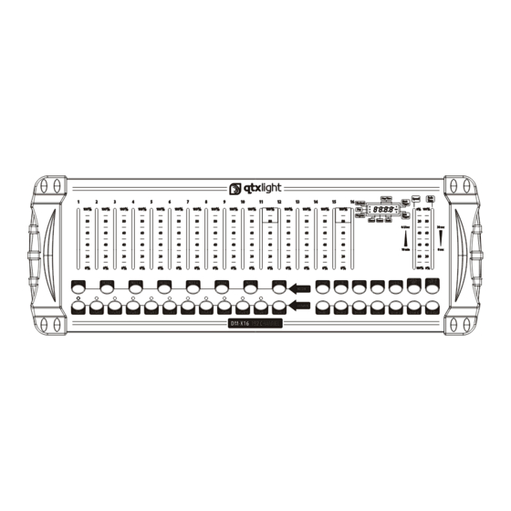
DMX 512 CONTROLLER SERIES 2. I NTRODUCTION NTRODUCTION 2.1 Features Features * DMX512/1990 Standard * Controls 12 intelligent lights of up to 16 channels, totally 192 channels * 30 banks, each with 8 scenes; 6 chase, each with up to 240 scenes * Record up to 6 chases with fade time and speeds * 16 sliders for direct control of channels * MIDI control over banks, chases and blackout... - Page 5 DMX 512 CONTROLLER SERIES Item Button or Fader Function Scanner select buttons Fixture selection Scanner indicator LEDS Indicates the fixtures currently selected Universal bump buttons representing scene Scene select buttons location for storage and selection For adjusting DMX values, Ch 1~16 can be adjusted immediately after pressing the respective scanner Channel faders select button...
-
Page 6: Product Overview (Rear Panel)
DMX 512 CONTROLLER SERIES 2.4 Product Overview (rear panel) Product Overview (rear panel) DMX 512 OUTPUT DMX 512 OUTPUT DC INPUT DC INPUT LAMP LAMP POWER POWER SERIAL NO : SERIAL NO : MIDI MIDI 9V 1000mA 1000mA 1=GROUND 2=DATA- 3=DATA+ DMX OUT DMX OUT DMX IN... -
Page 7: Common Terms
DMX 512 CONTROLLER SERIES 2.5 Common Terms 2.5 Common Terms The following are common terms used in intelligent light programming. Blackout is a state by where all lighting fixtures light output are set to 0 or off, usually on a temporary basis. -
Page 8: Fixture Addressing
DMX 512 CONTROLLER SERIES 3.1.2 3.1.2 FIXTURE ADDRESSING FIXTURE ADDRESSING Controller is programmed to control 16 channels of DMX per fixture, therefore the fixtures you wish to control with the corresponding SCANNER buttons on the unit, must be spaced 16 channels apart. -
Page 9: Resetting The System
DMX 512 CONTROLLER SERIES 3) Move one fader of 1-16 channel to select Notes : Notes : the pan channel. All pan/tilt can be reassigned to output on a 4) Press the TAPSYNC DISPLAY button to different DMX channel. select pan / tilt 5) Move one fader of 1-16 channel to select the tilt channel. -
Page 10: Operation
DMX 512 CONTROLLER SERIES 3.2 Operation 3.2 Operation 3.2.1 MANUAL MODE 3.2.1 MANUAL MODE The manual mode allows direct control of all scanners. You are able to move them and change attributes by using the channel faders. Action : Action : Notes : Notes : 1) Press the AUTO DEL button repeatedly until the... -
Page 11: Running A Program
DMX 512 CONTROLLER SERIES 3.3.3 RUNNING A PROGRAM 3.3.3 RUNNING A PROGRAM Action : Action : Notes : Notes : Use BANK UP/DOWN buttons to change Program Deselect Blackout if LED is lit. banks if necessary. Press the AUTO DEL button repeatedly until the AUTO LED turns on. -
Page 12: Chase Programming
DMX 512 CONTROLLER SERIES Chase Programming Chase Programming A chase is created by using previously created scenes. Scenes become steps in a chase and can be arranged in any order you choose. It is highly recommended that prior to programming chases for the first time;... -
Page 13: Edit Chase (Copy Scene Into Chase)
DMX 512 CONTROLLER SERIES 3.4.5 EDIT CHASE (COPY SCENE INTO CHASE) 3.4.5 EDIT CHASE (COPY SCENE INTO CHASE) Action : Action : Notes : Notes : Press and hold the PROGRAM button to enter programming mode. Press the desired CHASE button. Select the BANK that contains the scene to be copied using the BANK UP/DOWN buttons. -
Page 14: Delete All Chase Programs
DMX 512 CONTROLLER SERIES 3.4.9 DELETE ALL CHASE PROGRAMS 3.4.9 DELETE ALL CHASE PROGRAMS CAUTION! This procedure will result in irrevocable loss of chase step memory. The individual scenes and program banks will be preserved. Action : Action : Notes : Notes : Turn OFF controller. -
Page 15: Delete A Scene
DMX 512 CONTROLLER SERIES 3.5.3 DELETE A SCENE 3.5.3 DELETE A SCENE Action : Action : Notes : Notes : Press and hold the PROGRAM button to enter When deleting a scene the physical location is not programming mode. removed, however, all 192 DMX channels available to the scene will be set to value 0. -
Page 16: Blackout
DMX 512 CONTROLLER SERIES 3.6.3 BLACKOUT 3.6.3 BLACKOUT The Blackout button brings all lighting output to 0 or off. Midi Operation Midi Operation The controller will only respond to MIDI commands on the MIDI channel which it is set to full stop. All MIDI control is performed using Note on commands. -
Page 17: Appendix
DMX 512 CONTROLLER SERIES 4 APPENDIX 4 APPENDIX DMX Primer There are 512 channels in a DMX-512 connection. Channels may be assigned in any manner. A fixture capable of receiving DMX 512 will require one or a number of sequential channels. The user must assign a starting address on the fixture that indicates the first channel reserved in the controller. -
Page 18: Dmx Dipswitch Quick Reference Chart
DMX 512 CONTROLLER SERIES 4.3 DMX Dipswitch Quick Reference Chart 4.3 DMX Dipswitch Quick Reference Chart DMX Address Quick Reference Chart DMX Address Quick Reference Chart Dip Switch Position DMX DIP SWITCH SET 0=OFF 1=ON X=OFF or ON 128 160 192 224 256 288 320 352 384 416 448 480 129 161 193 225 257 289 321 353 385 417 449 481 130 162 194 226 258 290 322 354 386 418 450 482 131 163 195 227 259 291 323 355 387 419 451 483... -
Page 19: Technical Specifications
DMX 512 CONTROLLER SERIES 4.4 Technical Specifications Dimensions....................520 X183 X73 mm Weight........................... 3.0 Kg Operating Range..................DC 9V-12V 500mA min Maximum ambient temperature..................45 C Data input .................. locking 3-pin XLR male socket Data output ................locking 3-pin XLR female socket Data pin configuration ..............pin 1 shield, pin 2 (-), pin 3 (+) Protocols......................DMX-512 USITT 18/18...
Need help?
Do you have a question about the DM-X16 and is the answer not in the manual?
Questions and answers