Table of Contents
Advertisement
Quick Links
Advertisement
Table of Contents

Related Manuals for Greg Hanks Design BA-660

Summary of Contents for Greg Hanks Design BA-660
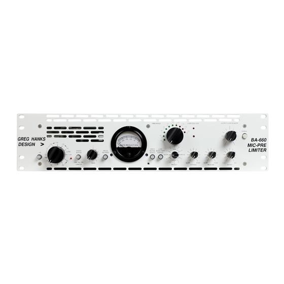
- Page 1 Issue GREG HANKS DESIGN BA-660 Operation and Service Manual...
- Page 2 C O N S C I E N T I O U S A U D I O D E S I G N A N D M A N U F A C T U R E Use and Care of your Mic Pre/limiter © Greg Hanks Design 35 Hardscrabble Hill Rd.
-
Page 4: Table Of Contents
Table of Contents Input meter select ..........11 TABLE OF CONTENTS ........I Gain Reduction bypass ........11 Preset/Manual ..........11 SUGGESTIONS FOR SAFETY ......2 Threshold ............11 Gain Cell Clip ..........12 SPECIFICATIONS..........3 Attack Time ...........12 Gain:.............. 3 Release Time ..........12 Input Impedance (20 Hz - 20 Khz) ....3 Ratio .............12 Frequency Response ........ -
Page 5: Suggestions For Safety
Suggestions for Safety replace your 2 pin receptacle. Do not - - Do not use ATER AND OISTURE defeat the purpose of this grounding- the unit near any source of water or in type plug by removing the grounding excessively moist environments pin. -
Page 6: Specifications
E) The unit does not appear to ) The unit has been dropped or operate normally or exhibits the enclosure exhibits marked change in performance; or significant damage. Specifications • • Gain: Attack Time - 200µs to 150 ms • Mic In Release Time - 15 ms - 6 sec >+97 db max. - Page 7 • Set the output gain makeup control for around the yellow LED. Line level use • Plug the Line level signal into the input of the BA-660. • Set the monitor selector switch to the input (in) position • Set the input selector and trim controls so that the signal is lighting the the Yellow on the peaks.
- Page 8 This page intentionally left blank-- BA660.doc 01/01/97 5 of 25...
-
Page 9: Overview I/O Connections
Overview I/O Connections IGNAL HASSIS RESET IDE CHAIN HAIN LAVORS COUPLE NPUT AC I UTPUT NBALANCE NSERT NSERT ELECTOR ETURN • made for phantom power and MIC In system will accept balanced or Accepts low impedance balanced single ended signals. Shield is signals between -70 and +14 expected to be served by the Nominal level. - Page 10 When active, this circuitry is ended input pick up it's reference from the limiting factor in the the output of the BA-660. The shield system headroom is source’d at pin 1 of the XLR. Pin 2 is •...
-
Page 11: Front Panel
• AC Input The IEC power input connector ties to a small PC board internally that carries a 2 Amp Slo Blo 3AG fuse and 100 VAC 120 VAC (Default) voltage selection to accommodate an input voltage range of 90 to 250 VAC. - Page 12 • These signals isolated from +48 V the main signal path with Switches phantom power on high voltage op-amps. When and off at the Mic input the insert points are not connector. Internal provision being used, we do not want is made for other voltages by to degrade the purity of the changing a zener diode.
- Page 13 removing all signals from the is accomplished, and when it unit, and adjusting until the is out the meter is looking at meter is at "0" the output of the unit as it feeds the outside world. "0" • • Limiter Tip In is equal to +4 dbu •...
- Page 14 The clip LED indicates that should be avoided by all but maximum attenuation of the the stout of heart, and gain cell has been reached. experimentation will provide This indicates when the with best amount of requested gain information regarding your control requires that the preferred settings.
-
Page 15: Overview Of Operation
∆ Provides balanced switching Set the output trim so of the incoming power line, that when metering output, approximately "0" pre-fuse. is obtained • Power switch Overview of Operation Setting the input level The input selector provides gain in 10 dB stepped increments, from - 65 to +14. - Page 16 Set threshold The threshold control is designed to provide a range of -40 to +20, with the "0" point occurring at the "0" LED. Threshold should be set with an exaggerated ratio control, because the gain reduction meter indicates how much limiting is going to occur, not where or when. After the threshold setting has been achieved, then the ratio control should be backed off to the point of auditory satisfaction.
-
Page 17: Output Level
SSL Quad limiter RCA BA-6 Manual Control. There are two positions for the presets, primary and trim. The primary position (lower) allows you Trim control of the threshold, with no control over the ratio, attack and release times. The “Trim” position (Upper) allows complete control over the threshold and trim over the ratio, attack and release. - Page 18 • Input and Output balance BA-660, but this is not recommended. Both the Mic, Line, insert return, side chain insert and ⇒ The Insert send sources the Line Output circuits are the shield.
- Page 19 120 VAC (Default) input it is imperative that the low side be disconnected from the ring and tied to the sleeve at the BA-660. The output drive is not ground current sensing, and should not drive ground. This WILL 220 VAC...
-
Page 20: Theory Of Operation
T H E D I A G R A M S . The best way to understand the operation of the BA-660 is to study the system drawing of the schematics. The boxed figures that indicate sheets are hierarchical symbols that relate directly and functionally. -
Page 21: System Gain Structure Control
cathodes. When the cathodes are shorted together the tube gain is almost the idealized Mu converted to db! When the unit runs out of range using degeneration, ( it is a somewhat noisy gain setting method at the lower ranges), pads are inserted and gain stages are eliminated to maximize signal to noise ratio and minimize total harmonic distortion. -
Page 22: Level Meter
Level Meter The 10 segment level meter employs a unique combination of 2 separate audio level meter circuits. The output of a VU driver and a Peak driver are hard wire Or'ed to obtain the dual metering function. In order to distinguish between the ballistics of the two metering circuits the visual intensity of each scale is varied according to signal level. -
Page 23: Output Stage
The tip in adjustment is necessary because the point that the tube conducts initially is both noisy and abrupt. This point varies greatly from one tube to another, which is why the offset voltage between the output of the gain control system and the point of conduction is adjustable. - Page 24 Warranty GREG HANKS DESIGN will repair or replace this product with new or rebuilt parts, free of charge in the USA or Puerto Rico in the event of a defect in materials or workmanship as follows: 1. Parts New or rebuilt parts in exchange for defective parts for the duration of the warranty of the unit, excluding vacuum tubes which carry a 6 month limited warranty.**...
Need help?
Do you have a question about the BA-660 and is the answer not in the manual?
Questions and answers