Table of Contents
Advertisement
Quick Links
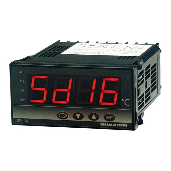
Digital Indicator
SD16A Series
Instruction Manual
Please ensure that this instruction manual is given to the final user of the
instrument.
Preface
Thank you for purchasing Shimaden products.
Please check that the delivered product is the correct item that you
ordered.
This instruction manual is meant for those who will be involved in the wiring,
installation, operation and routine maintenance of the SD16A series, and
describes about cautions, mounting, wiring, functions, and operation.
Please observe the contents, and always keep the manual close at hand
when handling this instrument.
The following headings give a description of matters requiring user
attention concerning safety, damage to machines and equipment,
additional explanations and commentaries are described under the
following headings.
Items concerning matters that may lead to
WARNING
an accident producing human injury or
death, if the warning is not observed.
Items concerning matters that may lead to
CAUTION
an accident producing damage to machines
or equipment, if the caution is neglected.
Note
Additional explanations and commentaries.
Note
Contents
Preface..................................................................................................... 1
Contents................................................................................................... 1
Safety Cautions........................................................................................ 1
1. Introduction .......................................................................................... 2
1-1. Check before use......................................................................... 2
1-2. Notes for use ............................................................................... 2
2. Installation and wiring ........................................................................... 2
2-1. Installation site (environmental conditions)................................... 2
2-2. Mounting...................................................................................... 2
2-3. External dimensions and panel cutout ......................................... 2
2-4. Wiring .......................................................................................... 2
2-5. Terminal arrangement .................................................................. 3
3. Names and functions for front panel..................................................... 3
3-1. Names ......................................................................................... 3
3-2. Functions ..................................................................................... 3
4. Measuring range code table ................................................................. 3
5. Error messages.................................................................................... 3
6. Instruction for each screen ................................................................... 4
6-1. Screen sequences ....................................................................... 4
6-2. Power ON Screen Group ............................................................. 5
6-3. Mode 0 Screen Group.................................................................. 5
6-4. Mode 1 Screen Group.................................................................. 5
7. Optional features overview ................................................................... 7
7-1. Alarm output ................................................................................ 7
7-2. Analog output............................................................................... 7
7-3. Sensor power supply ................................................................... 7
8. Specification......................................................................................... 8
Safety Cautions
WARNING
• The SD16A Series indicator is designed to indicate temperature,
humidity and other physical data for general industrial equipment. Do
not apply this instrument to other objects in a way that may cause
grave effects on human safety.
• In using this product, be certain to house it, for example, in a control
panel, so that the terminals cannot come into contact with personnel.
• Do not take this instrument out of its case or put your hand or any
conductor inside the case. Such conduct may lead to an accident that
endangers life or causes serious injury due to electric shock.
CAUTION
• To avoid damage to the connected equipment, facilities or the product
itself due to a fault of the product, safety countermeasure must be
taken before usage, such as proper installation of the fuse and the
overheating protection device.
• An alert symbol
is printed on the terminal nameplate attached to
the case. It warns not to touch the electrical charging parts when the
power is being supplied, so as to avoid the risk of electrical shock.
• Install a switch or breaker on the external source power circuit
connecting to the source power terminal as a means to shut down the
power.
The switch or breaker should be installed adjacent to the instrument
in a position that allows the operator easy access.
• Regarding the fuse:
Since this instrument has no built-in fuse, make sure to install a fuse
in the electric circuit connecting to the source power terminal.
Install the fuse in a position between the switch or breaker, and the
instrument and attach it to the L side of the source power terminal.
Fuse Rating: 250V AC 1.0A/Time-lag (T) or Medium Time-lag (M)
• The load of voltage and current to be applied to the output terminal
(analog output) and the alarm terminal must be within the rated
range. If the range is exceeded, the instrument will overheat causing
the risk of the instrument being damaged and its life reduced.
As for the rating, please refer to "8. Specification."
The unit connected to the output terminal should conform to the
requirements of IEC61010-1.
• Do not apply over-rated voltage or current to the input terminal. That
will cause the risk of the instrument being damaged and its life
reduced.
As for the rating, please refer to "8. Specification."
In case the input type is voltage (mV or V) or current (4 ~ 20mA), the
unit connected to the output terminal should conform to the
requirements of IEC61010-1.
• Take care to prevent metal or other foreign matter from obstructing
the ventilating hole for heat radiation. It will cause damage to the
instrument and may even result in fire.
• Do not block the ventilating hole. Also avoid dust accumulation. Any
rise in temperature or insulation failure may result in a risk of the
instrument being damaged and its life reduced. As for the clearance
space for installing the instrument, refer to "2-3 External dimensions
and panel cutout."
• Repeating withstanding tests on voltage, noise, surging may lead to
the deterioration of the instrument, so please be careful.
• Strictly refrain from remodeling and using the instrument improperly.
Copyright © SHIMADEN CO., LTD. All rights reserved.
1
MSD16A-E01-A
May. 2006
Advertisement
Table of Contents

Summary of Contents for Shimaden SD16A Series
-
Page 1: Table Of Contents
Digital Indicator WARNING SD16A Series • The SD16A Series indicator is designed to indicate temperature, humidity and other physical data for general industrial equipment. Do not apply this instrument to other objects in a way that may cause grave effects on human safety. -
Page 2: Introduction
1 copy • In case of thermocouple input, use a compensation wire with the type of thermocouple selected. The external resistance should be100Ω or Contact our local agent or exp-dept@shimaden.co.jp via less. Note e-mail for any problems about the product, accessories or •... -
Page 3: Terminal Arrangement
SD16A Instruction Manual 2-5. Terminal arrangement RS-232C RS-485 COM AL1 AL2 11 12 13 15 16 17 Power supply Inputs Voltage (V) Voltage (mV) Current (mA) Do not connect other than the specified input 100~ Note 240V AC AC/DC type to terminal. 50/60Hz 3. -
Page 4: Instruction For Each Screen
SD16A Instruction Manual 6. Instruction for each screen 6-1. Screen sequences Power ON Mode 0 Mode 1 Screen Group Screen Group Screen Group For approx. two secs Model name Basic screen Input type Alarm 1 Key lock latching release Measuring range lower-limit value Alarm 2 Display... -
Page 5: Power On Screen Group
SD16A Instruction Manual 0-3 PV bias 6-2. Power ON Screen Group The PV bias value is displayed or can be set. The following information is displayed automatically. The value is used for compensating input errors by Model name the sensor, etc. When the value is set, the compensated PV is displayed. - Page 6 So (scale over) is selected on Note LOC, COM Alarm 1 code screen (1-9). OFF, ON 1-18 Communication protocol The communication protocol is displayed or can be set. SHIM : Shimaden protocol ASC : MODBUS ASCII : MODBUS RTU SHIM, ASC, SHIM...
-
Page 7: Optional Features Overview
SD16A Instruction Manual Inhibit action 1-19 Communication address When the alarm output inhibit action is set to ON (on screen 1-11 or 1-14), The communication address is displayed or can the inhibit action at po wer on is performed, as follows. be set. -
Page 8: Specification
(sensor power supply), between alarm output and communication, or between alarm output and system. Not isolated between alarm output 1 and alarm output 2. Any questions should be directed to your local agent, or send an e-mail to exp-dept@shimaden.co.jp. Printed in Japan...
Need help?
Do you have a question about the SD16A Series and is the answer not in the manual?
Questions and answers