Advertisement
Table of Contents
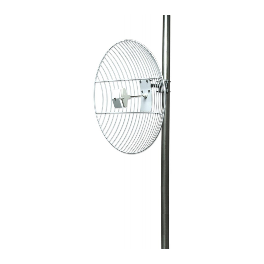
HigH-gain
OutdOOr
ParabOlic
grid antenna
QuicK inStall
guide
Model 503785
•
Ideal for long-distance,
outdoor, wireless
point-to-point
connections
of up to 15
km (9 mi.)
•
Weatherproof
and corrosion
resistant
•
Survives hurricane-force
winds up to 168 km/h (105 mph)
INTELLINET NETWORK SOLUTIONS
networking products. Ask your local computer dealer for more information or visit
All products mentioned are trademarks or registered trademarks of their respective owners.
www.intellinet-network.com
Copyright © INTELLINET NETWORK SOLUTIONS
Thank you for purchasing this
INTELLINET NETWORK
SOLUTIONS
Outdoor Parabolic Grid Antenna,
Model 503785.
Use it to avoid the cost and the
trouble of running outdoor cable
between buildings when you
expand your wireless network.
(Installation instructions on back.)
offers a complete line of active and passive
™
High-Gain
™
•
For either pole
or wall mounting
•
Lifetime
Warranty
.
INT-503785-miniQIG-0508-01
Advertisement
Table of Contents

Subscribe to Our Youtube Channel
Related Manuals for Intellinet 503785

Summary of Contents for Intellinet 503785
- Page 1 ™ networking products. Ask your local computer dealer for more information or visit www.intellinet-network.com Copyright © INTELLINET NETWORK SOLUTIONS All products mentioned are trademarks or registered trademarks of their respective owners. INT-503785-miniQIG-0508-01...
-
Page 2: Specifications
inStallatiOn* Fig. 1 Fig. 2 Fig. 3 Fig. 1 protruding through the grid. • Remove the nut from the feeder, • Line up the screws with the ensuring the O-ring remains on corresponding holes on the N- the feeder. type female connector/bracket •...
Need help?
Do you have a question about the 503785 and is the answer not in the manual?
Questions and answers