
Related Manuals for SpeakerCraft MODE 3.1

Summary of Contents for SpeakerCraft MODE 3.1
- Page 1 INSTALLATION INSTRUCTIONS MODE 3.1 Keypad TUNER 1 TUNER 1 TUNER 2 TUNER 2 IPOD 1: 30G VIDEO IPOD 1: 30G VIDEO IPOD 2: NANO IPOD 2: NANO DVD CHANGER DVD CHANGER CD CHANGER CD CHANGER REV 1...
-
Page 2: Safety Instructions
MODE 3.1 Installation Instructions Page 2 SAFETY INSTRUCTIONS CAUTION RISK OF ELECTRIC SHOCK DO NOT OPEN CAUTION: To reduce the risk of electric shock, do not remove cover, (or back). No user serviceable parts inside. Refer servicing to qualifi ed service personnel. -
Page 3: Table Of Contents
QUICK START GUIDE FOR SIMPLE MODE 3.1 EZ-TOOLS PROGRAMMING ........... 21 ADDING AN IPOD, MODE BASE AND MODE ADAPTER TO AN EXISTING PROJECT ........22 ADDING A MODE 3.1 KEYPAD TO AN EXISTING MZC PROJECT ..............25 PROGRAMMING SOURCE CONTROL ......................29 PROGRAMMING HARD KEYS ........................ -
Page 4: Introduction
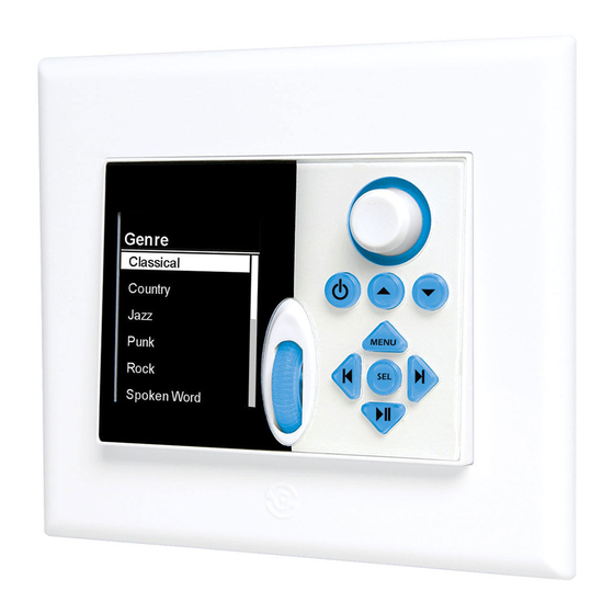
Keypad Setup options. The real beauty of the MODE 3.1 is that it is so easy to operate. A Scroll Wheel and Select Button allow navigation through and selection of the displayed menu options. Once a source has been selected, 8 back-lit programmable hard keys provide source control and on-screen menu navigation for sources such as DVD players, media servers, satellite receivers, cable boxes, etc. -
Page 5: Mode 3.1 Features
8. KEYPAD BEZEL - The keypad bezel is a screwless trim plate made of a plyable material that conforms to the surround- ing wall contour. The back of the bezel has form fi tting tabs that friction fi t the MODE 3.1 Mounting Bracket to provide a... -
Page 6: Rear Panel
3. KEYPAD PUNCH-DOWN BLOCK - 110 style punch- down terminal connects to the Zone Keypad Terminals on a SpeakerCraft MZC-66 or a KCM-1.0 when using MZC-88. 4. KEYPAD ANGLE TAB - Fits into the channeled lower Mounting Bracket Tab Slots to allow fl ush installation (fl at to wall surface) or with the lower portion of the keypad sloping away from the wall at about a 15°... -
Page 7: Mode Adapter Features
13. 24V DC - 2.1mm coaxial jack connects to a SpeakerCraft PS-3.0 24V Power Supply (Required/Not included). When stack- ing Adapters, one PS-3.0 will power up to 6 MODE Adapters. -
Page 8: Mode Base Features
MODE 3.1 Installation Instructions Page 8 MODE BASE FEATURES 1. BASE ALIGNMENT TAB - Two small tabs on the right side of the Base fi t into two small indents on the left side of an adjoin- 12V DC 1 AMP Adaptor Port Aux. - Page 9 MODE 3.1 Installation Instructions Page 9 10. SOURCE ID SWITCH - Carefully press with a pencil or other non-conductive probe to set the MODE Base to match the MZC Source Input to which it will be connect- ed. Source ID is displayed on the MODE Base LED.
- Page 10 MODE 3.1 Installation Instructions Page 10 RCA Interconnects MZC-66 EXPANSION PORT LOOP To Desired Source Inputs SOURCE 1 SOURCE 2 SOURCE 3 SOURCE 4 SOURCE 5 SOURCE 6 To Broadband Modem for Internet Connection EZ-PAD EZ-PAD EZ-PAD EZ-PAD EZ-PAD EZ-PAD...
-
Page 11: Wiring (Pre-Wire)
MZC system should be followed as described in the MZC-66 and 88 Installation Instructions. The information below will only detail those parts of an MZC System that pertain to the wiring requirements for connecting a MODE 3.1 Keypad, MODE Adapter and MODE Base. -
Page 12: Mode 3.1 Hard Button Configuration
Page 12 MODE 3.1 HARD BUTTON CONFIGURATION As received from the factory, MODE 3.1 Keypads have a pre- installed set of buttons that match the default button confi gu- ration in EZ-Tools. This default may not match the system be- ing installed. -
Page 13: Installation
Shelf Mount Follow the instructions above for Wall Mount. When positioning the Adapter, set it on the shelf, with the SpeakerCraft label side up and the red connection panel facing out for convenience in making connections. If using multiple Adapters, printing a small adhesive label identifying the source number and sticking it on the Adapter is suggested to assist in making connec- tions and troubleshooting. -
Page 14: Mode 3.1 Keypad
J-BOX NOTE: It is highly recommended that the MODE 3.1 Keypad be installed at a height of 56” on center. This provides the best overall position for optimum LCD viewing angle. This should be discussed with the homeowner prior to installation to avoid rework, should the homeowner fi... - Page 15 Keypad Angle There are two options for mounting the MODE 3.1. One is a fl ush installation with the keypad fl at to the wall surface, and the other is with the lower portion of the keypad sloping away from the wall at about a 15° angle. The angle mount creates a special cosmetic appeal and provides an improved LCD viewing angle.
-
Page 16: Connections
MODE Keypads. 5. When all connections have been made and confi rmed and the system is ready for operation, connect a SpeakerCraft PS-3.0 power supply (not included) to the 24V DC jack on the MODE Adapter. Plug the PS-3.0 into an unswitched... -
Page 17: Mode Adapter (Stacked)
MZC. These inputs must be confi gured in EZ-Tools and are only selectable from MODE Keypads. 6. When all connections have been made and confi rmed and the system is ready for operation, connect a SpeakerCraft PS- 3.0 Power Supply to the 24V DC Jack on one MODE Adapter. -
Page 18: Mode Base
Punch-Down Block The MODE 3.1 features a four pair punch-down block that allows fl exibility in wire options. CAT5 is recommended for typical use. The punch-down is color coded for CAT5 to assist in making connections. When making direct connections to the MZC, be sure to confi... - Page 19 Page 19 MODE 3.1 Connections 1. Strip approximately 1” to 1.5” from the outer jacket of the cable being connected to the MODE 3.1. DO NOT strip the individual conductors. 2. Using a proper punch-down tool, connect each of the wires to the matching color terminals on the MODE 3.1 punch- down block.
- Page 20 The Speaker Mute Relay is typically used in situations where a multi-channel amplifi er has been added to an MZC Zone Pre-out for additional rooms or ‘sub-zone expansion’. The MODE 3.1 Speaker Mute Relay gets connected to a SpeakerCraft EPR-1.0 Speaker Muting Relay. This allows the individual room keypads to mute their corresponding speaker pairs and not the zone, which would mute all of the rooms in the ‘sub-zones’.
-
Page 21: Programming With Ez-Tools
4. In the Zone Setup Window, left click Keypad. 5. Under Graphic Keypad, left click to place a check mark in the box next to MODE 3.1. If removing the EZ-Pad left click the MKP-1x box to uncheck the box and remove the EZ-Pad from the zone. Left click Apply. -
Page 22: Adding An Ipod, Mode Base And Mode Adapter To An Existing Project
MODE 3.1 Installation Instructions Page 22 13. Right click the Volume Up Arrow and then highlight and left click Punch Key’ s Commands to make the Volume Up Command available to all sources. Left click Yes in the pop-up. Repeat for Volume down. - Page 23 (Source 5). Only zones with MODE 3.1 Keypads will have access and control of the cable box (Source 5a) which will appear in the MODE 3.1 Main Menu as a regular Source. Further, as an option, the cable box can be unchecked in Zone Setup, for any zones other than the Family Room that get MODE 3.1...
- Page 24 MZC. 20. When Download is complete check EZ-Pads for proper iPod control. Make programming changes as needed by repeat- ing previous steps. 21. At this point, existing system functionality for EZ-Pads is updated and complete and MODE 3.1 programming begins.
-
Page 25: Adding A Mode 3.1 Keypad To An Existing Mzc Project
Source Setup and Zone Setup for proper system confi guration and perfor- mance. If only adding MODE 3.1’ s or upgrading EZ-Pads to MODE 3.1 Keypads, be sure to have followed all instructions for connections and installation in the previous sections. - Page 26 Any time there is more than one keypad in a zone, each of the keypads within that zone must be set to a different Address. Right click the EZ-Pad or MODE 3.1 icon in a par- ticular zone. Left click the EZ-Pad or MODE 3.1 Setup pop-up.
- Page 27 Virtual Button List Window When any source is selected on MODE 3.1, the information in the LCD will change to the Virtual Buttons associated with that source. Any menu or list of commands associated with controlling a particular device, or the system, can be confi gured for display.
- Page 28 MODE 3.1 Installation Instructions Page 28 To program the MODE 3.1 shown in Figure 24: 1. Left click the Tuner 1 Source Icon on the Virtual Keypad. It will highlight blue. This indicates the Tuner 1 ‘bank’ has been selected.
-
Page 29: Programming Source Control
PROGRAMMING SOURCE CONTROL The MODE 3.1 can be programmed to control any of the sources connected to a MZC 66/88 System by using either the Hard Keys or Virtual Buttons. Programming is consistent with standard EZ-Tools procedures. Hard Key programming should be for the most commonly used commands, Play, Skip, Channel Up/Down, etc. - Page 30 Left click OK to enter. 15. Repeat the previous steps to program the MODE 3.1 for all other sources using the appropriate Brand/Device com- mands for each source from the CMD Library. For commands not found in the Library, refer to MZC Installation Instruc-...
-
Page 31: Operating The Mode 3.1
MODE 3.1 Installation Instructions Page 31 OPERATING THE MODE 3.1 The following describes basic source, zone and system control in a typical MODE 3.1/MZC installation. Functions may vary given the programming options for the Hard keys and Virtual Buttons. POWER ON 1. - Page 32 MODE 3.1 Installation Instructions Page 32 Party Mode Pressing the Volume Knob for longer than 2 seconds will mute/un-mute the entire system, (all zones, speaker relay mutes) unless “This Zone Ignores Other Zone Initiations” is selected under Zone Setup/Whole House/Mute in EZ-Tools for a given zone. If selected, that zone MENU will ignore the Whole House Mute Commands.
-
Page 33: Zone Settings (Treble And Bass)
7. Press the Menu Button to return to the MODE Main Menu. KEYPAD SETTINGS In the MODE 3.1 Main Menu is an option called Keypad Settings. These settings are user defi nable preferences for keypad performance and appearance including: Button Intensity, LCD Intensity, Button Standby, LCD Standby, Beeper and Theme. -
Page 34: Keypad Reset
This setting selects different color schemes for the information displayed on the LCD. To adjust keypad settings: 1. In the MODE 3.1 Main Menu, highlight and select Keypad Settings using the Scroll Wheel and Click Button. 2. Using the Scroll Wheel, highlight the setting to be adjusted. -
Page 35: Specifications
MODE 3.1 Installation Instructions Page 35 SPECIFICATIONS MODE 3.1 Keypad Dimensions 3 5/8”W x 2 5/8”H x 1 5/16”D 3.1” High Resolution 16 bit Color LCD Hard Keys 7 back-lit, confi gurable programmable, 1 fi xed Menu Key System Connector... -
Page 36: Limited 2-Year Warranty
SpeakerCraft Inc. or a SpeakerCraft Inc. Authorized Dealer has been advised of the possibility of such damages, or for any claim by any other party. - Page 37 MODE 3.1 Installation Instructions Page 37 NOTES 940 Columbia Avenue, Riverside, CA 92507 (800) 448-0976 Fax (951) 787-8747 www.speakercraft.com...
Need help?
Do you have a question about the MODE 3.1 and is the answer not in the manual?
Questions and answers