
Summary of Contents for BIG ANGLE HEAD
- Page 1 ANGLE HEAD UNIVERSAL TYPE AGU30 OPERATION MANUAL Please be sure to read this manual before using the product. Consult the separate operation manual for Angle Head also regarding the general handling of the Angle Heads.
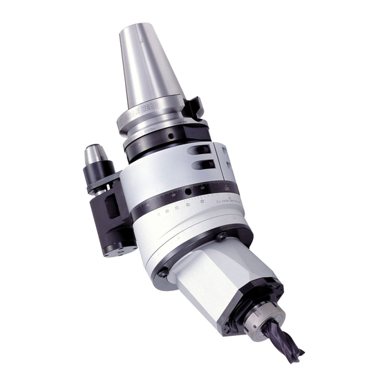
- Page 2 Equipment may also be damaged. Caution ANGLE HEAD Angle Head contributes to efficient machining by reducing setup times and production processes, allowing automatic tool change and full adjustment of the cutter head direction. SPECIFICATIONS...
-
Page 3: Specifications
SPECIFICATIONS #40 Taper Shank BBT, BIV, BDV, BCV40 SHANK Notes) 6,000 Maximum spindle speed (min The fixed length A varies according to the machining center model. Speed ratio (Body : Spindle) 1 : 1 If the unit is used for more than 30 minutes at a speed near the maximum spindle speed, it should be cooled by Forward Rotation direction... -
Page 4: Operation Sequence
OPERATION SEQUENCE The scale of the cutter direction Line marker Angles with Angles without Adjust the line marker to the cutter angle that you wish to set. How to adjust The angle without (example: 15 ) and the angle with the cutter angle (example: 15 ) indicate the same cutter angle. -
Page 5: Operation Procedures
OPERATION PROCEDURES How to adjust the cutter angle CAUTION Do not adjust the cutter angle while a cutting tool is mounted, as it is extremely dangerous to do so. Use the short head of the included hex key Connection Case (consult the CAUTION below) and loosen the (4) Clamping Bolts a little. - Page 6 CAUTION The Head Case may become stuck when swiveling. In this case, rotate the machine spindle manually and slowly to rotate the Angle Head’s spindle by a little. Rotate This will release the Head Case permitting it to rotate smoothly.
- Page 7 OPERATION PROCEDURES [If it is necessary to remove the Clamping Bolts] Structure’s view The structure of the turning Head Case Head Case is indicated in the picture to the right. For every 45° swivel, it is necessary to remove the Clamping Bolts and to substitute the position Connection Case...
- Page 8 Hold the Head Case by hand and swivel it to the selected angle. To set an angle, use the line marker on the Connection Case and the cutter angle’s scale on the Head Case. (Page 4 Fig. 2) Rotate the Setting Plate in order to match the screw holes of the Connection Case and tighten the (4) Clamping Bolts temporarily.
- Page 9 OPERATION PROCEDURES How to check the cutter direction Adjusting the cutter angle will also change the cutter direction. (Fig. 7) (Fig. 7) To check the cutter direction, follow the procedures below. Read the same value of the scale of the cutter direction with the value of the scale of the cutter angle you set, and check that the values of the scales match each other.
- Page 10 Install the Setting Disk enclosed in the Angle Head (Consult the page 11 “Installation of the cutting tool”) and loosen the (2) Side Clamping Screws a little while the Angle Head is mounted in the machine spindle. Please be aware that if the Side Clamping Screws are loosened too much, this allows clearance between the Body Case and the Adapter Case.
- Page 11 OPERATION PROCEDURES Insert the Adjusting Rods in the side holes of the Adapter Case, rotate the Adapter Case and Swivel adjust the cutter direction. (Fig. 12) It makes the adjustment easier to refer to the value of the scale of the cutter direction that was checked in the process [How to check the cutter direction] on page 8.
- Page 12 Tighten the (2) Side Clamping Screws uniformly with the hex key. CAUTION NEVER exceed the tightening torque by using an extension which may distort the Adapter Case. Changing the cutter angle will also change the cutter direction. Please pay enough attention when performing the adjustment process.
- Page 13 The maximum coolant pressure is 1MPa (142PSI). ] If the Angle Head is stored for an extended period after using a water-soluble coolant, it may be subject to rust. Blow air through the Locating Pin to remove the remaining coolant and pour anticorrosion oil from the Locating Pin prior to storage.
- Page 14 EXPORT DEPARTMENT TEL : ( +81 ) -72-982-8277 E-mail : export@big-net.ne.jp INTERNATIONAL TECHNICAL COMMUNICATION CENTER TEL : ( +81 ) -72-982-2730 E-mail : medep@big-net.ne.jp NO.0909...
Need help?
Do you have a question about the ANGLE HEAD and is the answer not in the manual?
Questions and answers