Table of Contents
Advertisement
Quick Links
w w w.apc.com
1
Connect Battery
For safety, the Back-UPS ES is shipped with one battery wire disconnected. The UPS will not operate until the wire is connected to the touch-safe
battery terminal. NOTE: Small sparks may occur during battery connection. This is normal.
1
Turn the Back-UPS ES over and press in the
two release tabs. Slide the plastic battery
cover off the unit.
Plastic Battery
Release Tabs
Cover
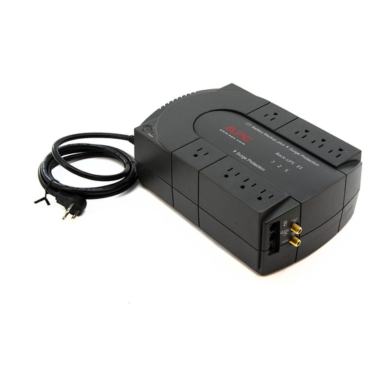
2
Connect
Battery Back-up plus
These outlets are powered whenever the Back-UPS ES is
switched ON. During a power outage or other utility problems
(brownouts, over-voltages), these outlets will be powered for a
limited time by the Back-UPS ES. Plug your computer,
monitor, CD-ROM drive and one other data-sensitive device
such as an external disk or tape drive, or Home Phoneline
Networking Association (HPNA) device into these outlets.
Power On
Surge Protection
These outlets provide full-time protection from surges even if the
Back-UPS ES is switched OFF. Plug your printer, fax machine,
scanner, or other peripherals that do not need battery power into
these outlets.
3
Power On and
Install Software
Press the ON/OFF switch to power the unit
ON.
A single short beep and the green "Power On"
indicator confirms the Back-UPS ES is on and
ready to provide protection.
The Back-UPS ES should charge for at least 16
hours to ensure sufficient runtime. The unit is
being charged whenever it is connected to utility
power, whether the unit is turned ON or OFF.
If the red Building Wiring Fault indicator (located
on the end near the power cord) is lit, your
building wiring presents a shock hazard that
should be corrected by a qualified electrician.
Install the PowerChute
software
Place the PowerChute Personal Edition CD-
ROM into your computer and follow the
installation instructions on the screen.
990-9219 Revision 1 7/02 Copyright © 2002 American Power Conversion Corp.
®
Equipment
Surge Protection
Battery Backup plus
Surge Protection
Surge Protection
Status Indications
The Back-UPS ES indicates operating status using a combination of visual and audible indicators.
On Line - UPS is supplying conditioned
utility power to the load
On Battery - UPS is supplying battery
power to the load connected to the
Battery outlets
Low Battery Warning - UPS is supplying
battery power to the load connected to
the Battery outlets and the battery is near
exhaustion
Replace Battery - Battery needs to be
checked and/or replaced, or battery is not
connected
®
Overload Shutdown - During On Battery
Personal Edition
operation a battery power supplied outlet
overload was detected.
Sleep Mode - During On Battery
operation the battery power has been
completely exhausted and the UPS is
waiting for utility power to return to
normal.
Building Wiring Fault - Your building
wiring presents a shock hazard that
should be corrected by a licensed
electrician.
Back-UPS ES 725
2
Connect the battery wire firmly to
the battery terminal.
Battery Wire
Battery Terminal
Place the Back-UPS ES to avoid:
- Direct sunlight
- Excessive heat
- Excessive humidity or contact with fluids
Plug the Back-UPS ES power cord directly into a wall outlet; not a surge
protector or power strip.
Connect Computer Cable
The supplied cable and software provide automatic file saving and shutdown of the
operating system in the case of a sustained power outage.
Connect the cable to the Data Port of the Back-UPS ES. Connect the other end of the
cable to the USB port on your computer. The software will automatically find the USB
Port of your computer.
Connect Modem / Phone / DSL / Fax / 10/100Base-T / HPNA / Cable Modem /
CATV or DSS to Surge Protection
The Back-UPS protects a single line (2-wire) phone (including Digital Suscriber Line -
DSL), Home Phoneline Networking Association (HPNA) type equipment, modem, 10/
100Base-T Ethernet, or fax machines from surges when connected through the UPS
as shown in the drawing below.
The UPS also protects a cable modem, CATV converter, or DSS receiver from surges
when it is connected through the UPS coaxial connectors as shown in the drawing
below.
FROM WALL JACK
DATALINE OUTPUT TO DSL,
MODEM, PHONE,
or NETWORK
(10/100BASE-T)
TO COMPUTER
USB PORT
Status
See the Troubleshooting section for additional assistance.
APC, Back-UPS and PowerChute are registered trademarks of American Power Conversion Corp.
®
3
Insert the battery back into the compartment.
Slide the plastic battery cover in place until the
two tabs lock into place.
WALL
CABLE OUT
OUTLET
CABLE OUTPUT TO CABLE
MODEM, CATV CONVERTER,
DSL / MODEM /
NETWORK / FAX
CABLE IN
CABLE INPUT FROM INTERNET
DATA PORT
SERVICE PROVIDER (ISP),
Circuit
Breaker
AC Line
Cord
Building Wiring
Fault Indicator
Visual Indications
Audible Indication
Power On LED - ON
None
Power On LED - ON
Beeping 4 times
(off during beep)
every 30 seconds
Power On LED -
Rapid beeping (one
Flashing
second intervals)
Power On LED -
Constant tone
Flashing
Power On LED - OFF
Constant tone
Power On LED - OFF
Beeping once every
4 seconds
Building Wiring Fault
None
LED (red) - ON
All other trademarks are property of their respective owners.
User's Guide
or DSS INPUT
CATV, or DSS
UPS Power
On Indicator
Power On
Power
Switch
Alarm Terminates
When
n/a
UPS transfers back to
On Line operation, or
when UPS is turned
off.
UPS transfers back to
On Line operation, or
when UPS is turned
off.
UPS turned off with
the power switch.
UPS turned off with
the power switch.
Utility power is
restored, or if utility
power is not restored
within 32 seconds, or
the UPS is turned off.
UPS is unplugged, or
plugged into a
properly wired outlet.
Advertisement
Table of Contents

Summary of Contents for APS Back-UPS ES 725 BE725BB
-
Page 1: Surge Protection
® ® Back-UPS ES 725 User’s Guide w w w.apc.com Connect Battery For safety, the Back-UPS ES is shipped with one battery wire disconnected. The UPS will not operate until the wire is connected to the touch-safe battery terminal. NOTE: Small sparks may occur during battery connection. This is normal. Turn the Back-UPS ES over and press in the Connect the battery wire firmly to Insert the battery back into the compartment. -
Page 2: Specifications
Use the table below to solve minor Back-UPS ES installation or operation problems. Consult APC Online Technical Support or call APC Troubleshooting Technical Support for assistance with problems that cannot be resolved using the table below: Problem Probable Cause Solution Back-UPS ES will not turn on.
Need help?
Do you have a question about the Back-UPS ES 725 BE725BB and is the answer not in the manual?
Questions and answers