Table of Contents
Advertisement
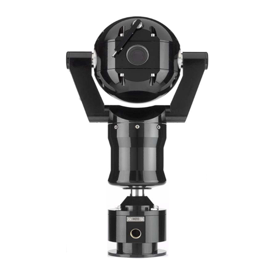
MIC1-440
Explosion Proof CCTV Camera System
Instruction Manual
All Rights Reserved. No part of this document may be reproduced or stored in a retrieval
system, or transmitted in any form or by any means, electronic, mechanical, photocopying,
recording or otherwise without the prior written permission of Forward Vision CCTV Ltd.
Neither Forward Vision CCTV Ltd nor its affiliates shall be liable to the purchaser of this
product or third parties for damages, losses, cost, or expenses incurred by the purchaser or
third parties as a result of: accident, misuse, or abuse of this product or unauthorised
modifications, repairs or alterations to this product, or failure to strictly comply with Forward
Vision CCTV Ltd operating and maintenance instructions.
Unit 1, Taplins Court
Church Lane, Hartley Wintney
Hants, RG27 8XU
Tel:+44-(0)-870 011 3131
Fax:+44-(0)-870 011 3132
www.fvcctv.co.uk
MIC1-440 Instruction Manual
Page 1 of 43
Issue 2
Advertisement
Table of Contents

Summary of Contents for Forward Vision CCTV MIC1-440
-
Page 1: Instruction Manual
Forward Vision CCTV Ltd. Neither Forward Vision CCTV Ltd nor its affiliates shall be liable to the purchaser of this product or third parties for damages, losses, cost, or expenses incurred by the purchaser or... -
Page 2: Table Of Contents
Appendix D List of approved repair centres Appendix E Installation Diagrams Drawings Revision record Issue Date Clause Revision Details Author 15/11/2005 First Issue 18/01/2007 App. E Armoured Cable Drawing added. Gland Type No Completed MIC1-440 Instruction Manual Page 2 of 43 Issue 2... -
Page 3: Introduction
The certification of this equipment depends upon the maintenance of the flamepaths (see note and table) and the use of the following materials in the construction. MIC1-440 Instruction Manual Page 3 of 43 Issue 2... - Page 4 SIRA05ATEX1300X Exd IIC Ta –20 +60 The unit shall only be installed and brought into service using the operating parameters defined in these instructions and in the technical specifications see page 22 MIC1-440 Instruction Manual Page 4 of 43 Issue 2...
-
Page 5: Installation
MIC-440 can work up to 25 meters from its power supply. This means that if the power supply can be placed within a non-hazardous area within 25 meters of the MIC unit a standard power supply can be used (see Fig 1). FIG 1 MIC1-440 Instruction Manual Page 5 of 43 Issue 2... -
Page 6: Unpacking The Camera
The cable is required to connect the MIC-440 to its power source, control data and video. This composite cable consists of two pairs (24AWG) plus 4 cores (22 AWG), 2 Cores (24 AWG) and one coax cable for the video signal. MIC1-440 Instruction Manual Page 6 of 43 Issue 2... -
Page 7: Electrical Connections
Video output signal conforms to CCIR PAL 1V Composite format. (NTSC format is available on request). Telemetry signals all conform to the RS485 / RS422 standard. The unit continuously monitors incoming telemetry whether in full or half duplex mode. MIC1-440 Instruction Manual Page 7 of 43 Issue 2... -
Page 8: Earthing The Camera
The unit is supplied with an industrial standard 4” (101.6mm) PCB mounting base and can be mounted on standard CCTV mounting brackets or on tailor made mounting brackets. Forward Vision CCTV. Can supply suitable brackets if required. M8 Stainless steel nuts, bolts and washers should be used to secure the base of the MIC unit to the selected mounting bracket. -
Page 9: Connection Between The Camera And The Terminal Box
Coax Core Video HD3-8 VIDEO Coax Screen Video Return HD3-9 Black Tamper Switch HD3-10 Tamp Sw Orange Wash HD3-11 Wash Brown 0v rtn Tamp Sw HD6-1 Grey 0v rtn Wash HD6-2 MIC1-440 Instruction Manual Page 9 of 43 Issue 2... -
Page 10: Telemetry Connections
Telemetry lines, as this would increase the load on these lines reducing the number of cameras that can be driven by a single telemetry drive. MIC1-440 Instruction Manual Page 10 of 43 Issue 2... -
Page 11: Commissioning The Camera Using Camset
No. loaded into the camera. The text on screen message appear in red and looks similar CAM 1 SW 22AUG120GW Where “CAM 1” is the current address of the camera. MIC1-440 Instruction Manual Page 11 of 43 Issue 2... - Page 12 If non-ASCII characters are seen for the software version No, this indicates that there is a duplication of the camera address on the network with the address that produces the corrupted response. MIC1-440 Instruction Manual Page 12 of 43 Issue 2...
- Page 13 This mechanism allows any of the special function presets to be executed. See Appendix C for a complete list of special preset codes. MIC1-440 Instruction Manual Page 13 of 43 Issue 2...
- Page 14 Setup window and can only be used if the 8 or 10 channel alarm scan card is fitted to the power supply box. Normally Set to Multi Alarm off to prevent inconsistent operation of the camera. MIC1-440 Instruction Manual Page 14 of 43 Issue 2...
- Page 15 Values set in the box represent the following settings: MIC1-440 Instruction Manual Page 15 of 43 Issue 2...
- Page 16 Auto IR ON/OFF and Auto Integration ON/OFF These commands go directly to the 780 module unlike the functions under Setups. Which correctly adjusts the 480 camera module and control card operation. LENS RECALIBRATION. Is not used on this unit. MIC1-440 Instruction Manual Page 16 of 43 Issue 2...
- Page 17 See Appendix A, Connecting CamSet to set up different adaptors for operation with the CamSet Programme. Forward Vision CCTV Ltd also provide their own front-end control system for use with this camera. The software runs on an IBM compatible PC and is called WinCam. Further details on this product are available on request.
- Page 18 Sony FCB480 module camera. If these presets are not accessible via the main control systems then Forward Vision CCTV has a small freely available IBM /PC compatible programme called SonySet that allows these camera presets to be set up and tested.
- Page 19 This is a list of all the possible commands. You can arrange 10 presets with 10 of the following commands in each. Presets are recalled with standard Goto Preset commands. Camera preset 1 is preset 240; camera preset 2 is preset 241 etc, etc. MIC1-440 Instruction Manual Page 19 of 43 Issue 2...
-
Page 20: Camera Preset Commands
+1 gain: -1 gain: set bright: reset bright: +1 bright: -1 bright: set exposure comp: reset exposure comp: +1 exposure comp: -1 exposure comp: set exposure comp: on exposure comp: off MIC1-440 Instruction Manual Page 20 of 43 Issue 2... -
Page 21: Maintenance
10 Camera setup presets. Simplex, half and full duplex operation. Up to 10 external alarms and 2 output relays (optional). External washer pump drive (optional). Compatible with many proprietary protocols (see protocol list). MIC1-440 Instruction Manual Page 21 of 43 Issue 2... -
Page 22: Appendix A. Connecting Mic1- 440 For Testing Purposes
200mtrs then +9vDC power can be fed to pin 9 of the RS232 side of the KK adaptor (0v to pin 5). Care should be taken to ensure that +9v does not get to pin 9 of the PC comm port connector. MIC1-440 Instruction Manual Page 22 of 43 Issue 2... - Page 23 If the Notebook does not have a serial Comm port then the USB port can be used and a USB to RS232 adaptor installed. Usually this will be mapped to Comm 3 or Comm 4 by the USB driver software. MIC1-440 Instruction Manual Page 23 of 43 Issue 2...
-
Page 24: Appendix B. Types Of Telemetry Connection
This type of connection is most suitable for connection to a fibre interface unit for long distance transmission to the control station. Four wire connections are generally preferred by third party microwave and radio interface equipment too. RS485 two wire half duplex operation. MIC1-440 Instruction Manual Page 24 of 43 Issue 2... - Page 25 This type of link might typically be used where the reduction in functionality is not an issue and telemetry is transmitted in simplex form over the copper video cable as an FSK sub-carrier by third party FSK system manufacturers. MIC1-440 Instruction Manual Page 25 of 43 Issue 2...
-
Page 26: Appendix C Special Preset Codes
Learn preset 218 WASHWIPE_ON_PRESET Learn preset 219 WASHWIPE_OFF_PRESET Learn preset 220 Auto wash-wipe Go to preset 62* AUTO_ALARM_ON_PRESET Learn preset 236 AUTO_ALARM_OFF_PRESET Learn preset 237 Auto alarm goes to preset position 63 MIC1-440 Instruction Manual Page 26 of 43 Issue 2... - Page 27 CAMERA_COMMAND_PRESET10 go to preset 249 default: normal settings These can be changed with SonySet CAMERA MODULE RESET Learn PRESET 251* ON SCREEN MENU (Toggle on/off) Learn preset 254 MIC1-440 Instruction Manual Page 27 of 43 Issue 2...
- Page 28 5 minutes got preset 48 22 off 23 on Auto white balance 23 off Outdoor white balance Goto Preset: 50 manual focus 52 digital zoom 54 manual exposure on 56 auto low light 58 wiper MIC1-440 Instruction Manual Page 28 of 43 Issue 2...
- Page 29 86 long fast 87 long med 88 long slow 90 re program 2 91 re program 3 92 auto home on 93 auto home off 94 Auto white balance 95 Outdoor white balance MIC1-440 Instruction Manual Page 29 of 43 Issue 2...
- Page 30 Learn presets 118 and 119. Softstop Learn Preset 120,121. Non Dwell zone Learn Preset 122,123. Auto low light mode. Learn presets 124, 125. Address change Learn preset 126 twice then learn address as preset. MIC1-440 Instruction Manual Page 30 of 43 Issue 2...
- Page 31 To reverse pan direction for when camera is mounted upside down, learn preset 95. To change camera address, learn preset 99 twice and learn new address as preset. WIPER continuous PRESET (Toggles on off) WIPER 5 second interval PRESET WIPER 30 second interval PRESET MIC1-440 Instruction Manual Page 31 of 43 Issue 2...
- Page 32 For use with ADPRO fixed speed units: NO SPEED. Learn Preset 111 Fix speed at 5: Learn preset 101 Fix speed at 255: Learn preset 110 Allow variable speed: Learn preset 112 MIC1-440 Instruction Manual Page 32 of 43 Issue 2...
- Page 33 There are six independent tours. Switch the current tour by learning presets 51 to 56 SET_TOUR1_PRESET SET_TOUR2_PRESET SET_TOUR3_PRESET SET_TOUR4_PRESET SET_TOUR5_PRESET SET_TOUR6_PRESET AUTOFLIP_ON_PRESET AUTOFLIP_OFF_PRESET WASHWIPE_ON_PRESET WASHWIPE_OFF_PRESET PRIVACY_PRESET_START PRIVACY_PRESET_END PRIVACY_SET_WHOLE PRIVACY_CLEAR_WHOLE PRIVACY_UNCOVER_ALL PRIVACY_REPLACE_ALL PRIVACY_SHOW_STYLE PRIVACY_HIDE_STYLE PRIVACY_SET_STYLE PRIVACY_SET_CENTRAL PRIVACY_CLEAR_CENTRAL PRIVACY_SHOW_CURSOR PRIVACY_HIDE_CURSOR PRIVACY_SAVE_PARAMETER PRIVACY_LOAD_PARAMETER MIC1-440 Instruction Manual Page 33 of 43 Issue 2...
- Page 34 AUTO_LOWLIGHT_OFF_PRESET CAMERA_RECALIBRATE_PRESET RESET_PRESETS_PRESET These are the camera presets programmed with the SonySet program. To activate the programmed setups GOTO these presets: CAMERA_COMMAND_PRESET1 CAMERA_COMMAND_PRESET2 CAMERA_COMMAND_PRESET3 CAMERA_COMMAND_PRESET4 CAMERA_COMMAND_PRESET5 CAMERA_COMMAND_PRESET6 CAMERA_COMMAND_PRESET7 CAMERA_COMMAND_PRESET8 CAMERA_COMMAND_PRESET9 CAMERA_COMMAND_PRESET10 MIC1-440 Instruction Manual Page 34 of 43 Issue 2...
- Page 35 WASHWIPE_ON_PRESET Learn Preset 78 WASHWIPE_OFF_PRESET Learn Preset 79 For units mounted like a dome, the left and right is reversed. Set this by learning preset 80 INVERTED Learn Preset 80 UPRIGHT Learn Preset 81 MIC1-440 Instruction Manual Page 35 of 43 Issue 2...
- Page 36 These preset codes are reserved for the Hi. Res. Privacy overlay card. #define PRIVACY_SET_WHOLE #define PRIVACY_CLEAR_WHOLE #define PRIVACY_UNCOVER_ALL #define PRIVACY_REPLACE_ALL #define PRIVACY_SHOW_STYLE #define PRIVACY_HIDE_STYLE #define PRIVACY_SET_STYLE #define PRIVACY_SET_CENTRAL #define PRIVACY_CLEAR_CENTRAL #define PRIVACY_SHOW_CURSOR #define PRIVACY_HIDE_CURSOR #define PRIVACY_SAVE_PARAMETER #define PRIVACY_LOAD_PARAMETER #define PRIVACY_INIT_PARAMETER #define PRIVACY_SET_CURSOR MIC1-440 Instruction Manual Page 36 of 43 Issue 2...
-
Page 37: Appendix D List Of Approved Repair Centres
APPENDIX D LIST OF APPROVED REPAIR CENTRES REPAIR CENTRE ADDRESS TELEPHONE E-MAIL ADDRESS Unit 1, Taplins Court FV CCTV LTD 0870 0113131 SALES@FVCCTV.CO.UK Church Lane Hartley Wintney Hants RG27 8XU MIC1-440 Instruction Manual Page 37 of 43 Issue 2... -
Page 38: Appendix E Installation Diagrams
P/No JB EExd Interface Item 06 Exd Barrier Glands (not supplied) P/no To be selected by installer to match incoming cables. Item 07 Mounting Bracket Heavy Duty (Not supplied) P/no FVMB MIC1-440 Instruction Manual Page 38 of 43 Issue 2... - Page 39 P/No JB EExd Interface Item 06 Exd Barrier Glands (not supplied) P/no To be selected by installer to match incoming cables. Item 07 Mounting Bracket Heavy Duty (Not supplied) P/no FVMB MIC1-440 Instruction Manual Page 39 of 43 Issue 2...
- Page 40 P/No JB EExd Interface Item 06 Exd Barrier Glands (not supplied) P/no To be selected by installer to match incoming cables. Item 07 Mounting Bracket Heavy Duty (Not supplied) P/no FVMB MIC1-440 Instruction Manual Page 40 of 43 Issue 2...
-
Page 41: Drawings
DRAWINGS Fig 1. Four wire full duplex RS422 operation. Fig 2. Two wire half duplex RS485 operation. Fig 3. Two wire simplex RS485 operation MIC1-440 Instruction Manual Page 41 of 43 Issue 2... - Page 42 Fig 5. Forward Vision CCTV terminal box layout showing space where washer card is fitted. MIC1-440 Instruction Manual Page 42 of 43 Issue 2...
-
Page 43: Mic1-440 Instruction Manual
Fig 6. Terminal Box Schematic. MIC1-440 Instruction Manual Page 43 of 43 Issue 2...
Need help?
Do you have a question about the MIC1-440 and is the answer not in the manual?
Questions and answers