
Related Manuals for Vaisala HMT360Series


Summary of Contents for Vaisala HMT360Series
- Page 1 HMT360 Series Transmitters for Hazardous Areas UIDE M010056EN-D May 2004...
- Page 2 Finland Visit our Internet pages at http://www.vaisala.com/ © Vaisala 2004 No part of this manual may be reproduced in any form or by any means, electronic or mechanical (including photocopying), nor may its contents be communicated to a third party without prior written permission of the copyright holder.
-
Page 3: Table Of Contents
Table of Contents CHAPTER 1 GENERAL INFORMATION................6 Safety..................6 ESD Protection..............6 Version Information ..............7 Warranty ..................7 CHAPTER 2 GENERAL ...................... 8 Output quantities..............8 Probe options ................8 Maintenance................9 Compliance with the requirements ........10 European requirements............ -
Page 4: Vaisala
CALIBRATION AND ADJUSTMENT ............45 Calibration interval ..............45 Factory calibration and adjustment........45 Calibration and adjustment by the user .......45 Calculating the correspondence of current values and output quantities..............47 Relative humidity calibration..........48 Automatic two-point calibration (only with HMT360 with display) ................48 Vaisala __________________________________________________________________________ 4... - Page 5 HMT361................59 HMP362 ................59 HMP363 ................60 HMP364 ................60 HMP365 ................60 HMP368 ................60 APPENDIX 2: WIRING FOR INTRINSICALLY SAFE OPERATION, FM ... 63 APPENDIX 3: WIRING FOR INTRINSICALLY SAFE OPERATION, CSA. 64 CERTIFICATES.................... 65 Vaisala __________________________________________________________________________ 5...
-
Page 6: Chapter 1 General Information
Note highlights important information on using the product. ESD Protection Electrostatic Discharge (ESD) can cause immediate or latent damage to electronic circuits. Vaisala products are adequately protected against ESD for their intended use. However, it is possible to damage the product by delivering electrostatic discharges when touching, removing, or inserting any objects inside the equipment housing. -
Page 7: Version Information
M010056EN-D 5th version, May 2004 Warranty For certain products Vaisala normally gives a limited one-year warranty. Please observe that any such warranty may not be valid in case of damage due to normal wear and tear, exceptional operating conditions, negligent handling or installation, or unauthorized modifications. -
Page 8: Chapter 2 General
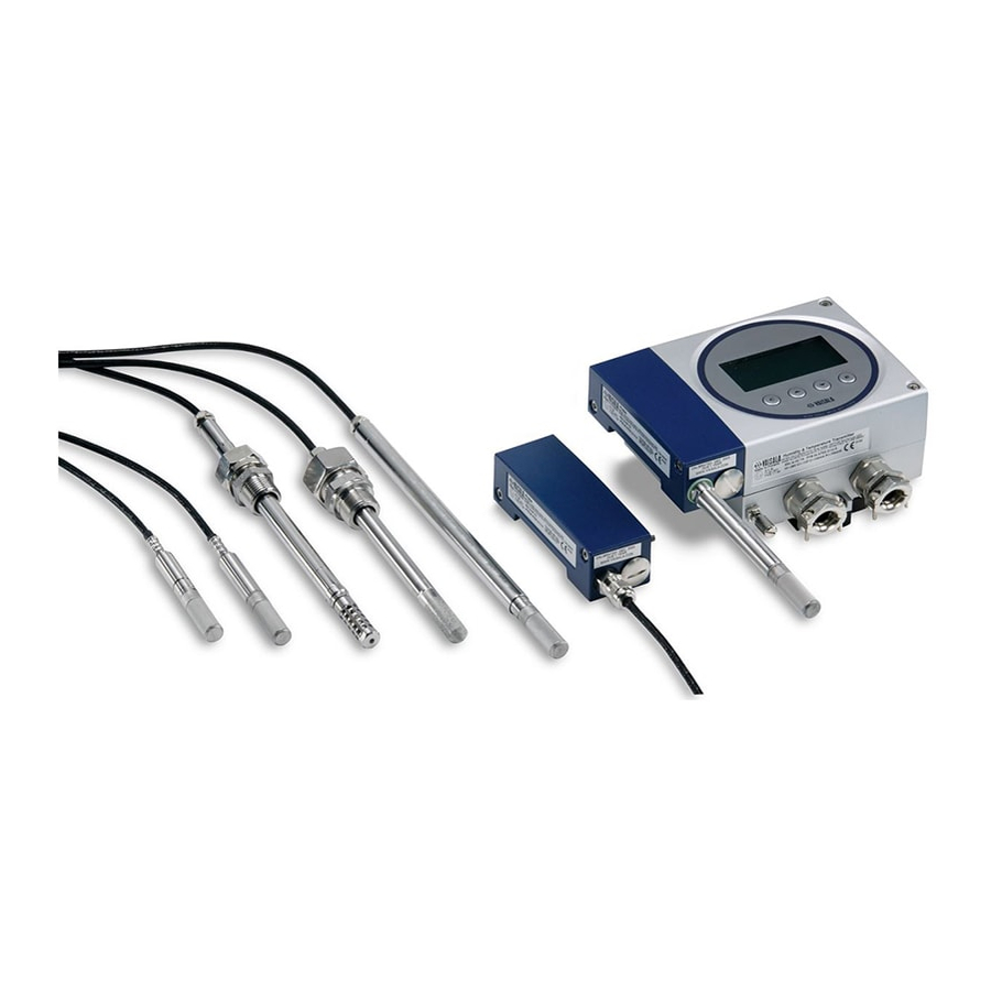
The available quantities are described in Table 2 on page 35. Probe options The HMT360 transmitter series has various options for transmitter units, sensor heads and cable lengths (2.5 and 10 m). The available probe types are the following: HMP361 HMP362 HMP363 HMP364 HMP365 HMP368 Vaisala __________________________________________________________________________ 8... -
Page 9: Maintenance
44 for detailed information. All other maintenance is performed at the factory. If a transmitter is damaged, contact Vaisala or Vaisala distributor and send the instrument to the addresses below: Please, include a short description of the fault and the date and place of purchase. -
Page 10: Compliance With The Requirements
CSA approved for Class I, Division 1 and 2, Groups A, B, C, D; Class II Division 1 and 2, Groups G and Coal Dust; Class III. Intrinsically safe when connected as shown in Appendix 3. Australian requirements (TestSafe) TestSafe approved for Ex ia IIC T5 IP65 (Zone 0). Vaisala _________________________________________________________________________ 10... -
Page 11: Chapter 3 Installation
Select a place with stable conditions for mounting the transmitter. Do not expose the transmitter to direct sunlight or rain. A rain shield for HMT360 transmitter is available. When mounting the sensor head, select a place representing the process conditions. Vaisala _________________________________________________________________________ 11... -
Page 12: Temperature Differences
However, never use the sensor long periods without the filter as this may cause a faster contamination of the sensor. The transmitter fulfils the specified EMC regulations with the protective filter on the sensor head. Vaisala _________________________________________________________________________ 12... -
Page 13: Mounting The Transmitter
3. probe; including a part of measurement electronics (e.g. calibration memory and the sensor head) 4. protective covers 5. flat cable 6. sensor head 7. cable glands 8. grounding terminals 9. RS232 connector Different parts of the transmitter IGURE Vaisala _________________________________________________________________________ 13... -
Page 14: Mounting The Probes
When sampling in pressurized processes, the sampling cell HMP302SC is available as an optional accessory. HMP362 installation (without the sampling cell) Screws, hexagon socked head (provided) Threaded sleeve HMP362 Probe (not provided) O-Ring (provided) Process pipe or chamber Threaded sleeve Vaisala _________________________________________________________________________ 14... -
Page 15: The Hmp363 Probe For Confined Spaces
The distance between the sensor and the channel wall can be adjusted. The adjustment range is 100 - 320 mm, measured from the tip of the sensor head to the flange. Vaisala _________________________________________________________________________ 15... -
Page 16: The Hmp365 Probe For High Temperatures
This probe is also available for dewpoint measurements in natural gas. The probe is provided with a nut, a fitting screw and a sealing washer to make the installation easier. Vaisala _________________________________________________________________________ 16... - Page 17 Change the sealing washer every time the fitting screw is detached. Use high-vacuum grease (e.g. Down Corning, Europe) or a similar grease. 1. fitting screw 2. sealing washer 3. tightening cone 4. clean cotton stick Vaisala _________________________________________________________________________ 17...
- Page 18 If the HMP364 is installed in a process with a pressure differing from normal atmospheric pressure, please enter the pressure value of the process (in hPa or mbar) into the transmitter memory via the serial line (see page 42) or via the display/keypad (see page 33) . Vaisala _________________________________________________________________________ 18...
-
Page 19: The Hmp368 Probe For Measuring Humidity In Pressurized Pipelines Or Moisture In Liquids
(see page 42) or via the display/keypad (see page 33). • Make sure that the temperature at the measurement point is equal to that of the process, otherwise the humidity reading may be incorrect. Vaisala _________________________________________________________________________ 19... -
Page 20: Tightening The Clasp Nut
3. Mark the fitting screw and the clasp nut. 4. Tighten the nut a further 50 - 60° (ca.1/6" turn) with a fork spanner. If you have a suitable torque spanner, tighten the nut to 45±5 Nm (33±4 ft-lbs). Vaisala _________________________________________________________________________ 20... -
Page 21: Installing The Probe Through The Ball Valve Assembly
This installation makes it unnecessary to empty or shut down the process for installing or removing the sensor head. Use the Vaisala DMP248BVS ball valve set or a 1/2" ball valve assembly with a ball hole of ∅14 mm or more. - Page 22 10 bar. With 10...40 bar pressures you must shut down the process before installing or removing the probe. The maximum operation pressure for the probe HMP368 is 40 bar. Vaisala _________________________________________________________________________ 22...
-
Page 23: Electrical Connections
When using the transmitter in hazardous places, the use of galvanic isolators or barriers is essential. The following barrier & isolator are available in Vaisala: barrier No. 210664 (STAHL 9001/51-280-091-141) for USA&Canada and galvanic isolator No. 212483 (STAHL 9160/13-11-11) or barrier No. 210664 for EU. -
Page 24: Installation In Hazardous Locations
= 20 mA*(45+340)ohm + 1 V = 8.7 V drop Ctot barrier Voltage for R = 24 V - 12 V - 8.7 V = 3.3 V drop Maximum load = 3.3 V / 20 mA = 165ohm , R < 165ohm lmax lmax Vaisala _________________________________________________________________________ 24... -
Page 25: Hmt360 Connected To A Galvanic Isolator
I = 4...20mA a) current signal controller HAZARDOUS AREA SAFE AREA Power Supply C H 1 Galvanic C H 2 Separator Controller U = I*Rl b) voltage signal controller . HMT360 connected to a galvanic isolator. FIGURE 4-1 Vaisala _________________________________________________________________________ 25... -
Page 26: Hmt360 Connected To A Zener Barrier
I = 4...20mA a) current signal controller HAZARDOUS AREA SAFE AREA C H 1 C H 2 Zener Power Supply Barrier Controller U = R x I b) voltage signal controller HMT360 connected to a zener barrier. FIGURE 4-2 Vaisala _________________________________________________________________________ 26... -
Page 27: Examples Of Connections
18...31,2VDC galvanic isolator ! Load Ch2 STAHL 9160/13-11-11 (galvanic isolator). FIGURE HAZARDOUS AREA SAFE AREA HMT360 Connection board -Ch1+ -Ch2+ STAHL 9001/51-280-091-141 20...35 VDC Load Ch1 20...35 VDC Load Ch2 STAHL 9001/51-280-091-141 (zener barrier). FIGURE Vaisala _________________________________________________________________________ 27... -
Page 28: Grounding
Note that the allowed resistance between barrier and system ground must be less than 1 ohm. See the figure below. HAZARDOUS AREA SAFE AREA -Ch2+ -Ch1+ Zener Instrument Barrier system Barrier ground System ground Grounding. FIGURE Vaisala _________________________________________________________________________ 28... -
Page 29: Chapter 5 Operation
In normal operation it is not lit. If the LED is lit and all calibration or test dip switches are disabled, it is an indication of an internal error. Vaisala _________________________________________________________________________ 29... -
Page 30: Dip Switch Functions
If this switch is in the EEPROM DISABLED position (down), it does not allow any calibrations or scalings. NOTE Keep this switch always in the disabled position during normal use of the transmitter! Vaisala _________________________________________________________________________ 30... - Page 31 Note that only the ordered quantities can be selected. option gives you the choice of setting any ordered SPECIAL quantity to each channel. NOTE Always restore the dip switch settings after having tested the analog outputs or performed the calibration. Vaisala _________________________________________________________________________ 31...
-
Page 32: Chapter 6 Operation Errors
Cleaning the sensor from glycol in a natural gas application ® If a glycol layer on the VAISALA HUMICAP sensor is disturbing the moisture measurement, the sensor can be cleaned on site soaking the sensor to de-ionized water or to IPA (isopropanol, propan-2-ol). - Page 33 The water or IPA temperature must be below 30 °C (86 °F). Do not use a cotton stick or any other mechanical means for cleaning and/or drying the sensor. In case of constant error, please contact Vaisala Service (see Chapter 2: Maintenance). Vaisala _________________________________________________________________________ 33...
-
Page 34: Display/Keypad Commands
Adjust the pressure reading with buttons ▲ and ▼. Acknowledge the value with button E. To complete the pressure setting, turn the dip switch back to position (down). DISABLED See the pressure conversion table on page 42. Vaisala _________________________________________________________________________ 34... -
Page 35: Selecting The Output Quantities
Selecting the analog outputs You can select the output quantities for channels 1 and 2 by turning the transmitter's dip switch to CALIBRATION ENABLED DISABLED position (up) and the three dip switches ENABLED OUTPUT SELECTION to position (all up). SPECIAL Vaisala _________________________________________________________________________ 35... - Page 36 If the transmitter is equpped with two analog channels, select the quantity for channel 2 in the same way, for example: Press button C to exit the display command mode or continue by setting the pressure. NOTE Remember to restore the dip switch settings. Vaisala _________________________________________________________________________ 36...
-
Page 37: Scaling The Analog Outputs
This menu starts automatically after the scaling menu only if the dip switches are on the OUTPUT SELECTION position (all up) from the beginning. SPECIAL NOTE Remember to restore the dip switch settings. Vaisala _________________________________________________________________________ 37... -
Page 38: Chapter 8 Serial Interface
If the transmitter does not receive any commands for half an hour, it automatically closes the serial communication. Serial communication settings Serial communication settings ABLE parameter value bauds 2400 parity none data bits stop bits Vaisala _________________________________________________________________________ 38... -
Page 39: Selecting The Analog Outputs
Available only for HMT368H for moisture measurements in liquid. Available only for HMT360N for natural gas Example: >asel rh t ↵ Ch1 RH 0.00 %RH Ch1 RH 100.00 %RH Ch2 T -40.00 'C Ch2 T 60.00 'C > Vaisala _________________________________________________________________________ 39... -
Page 40: Scaling The Analog Outputs
Note that HMT360 for natural gas can be checked but not adjusted by a user. Relative humidity adjustment NOTE Read also the calibrator e.g. HMK15 manual and refer to page 47 of this manual for more detailed instructions on salt bath calibration. CRH ↵ Vaisala _________________________________________________________________________ 40... -
Page 41: Temperature Adjustment
2. Reconnect the serial cable. Type the multimeter reading and press ↵. 3. Type the higher current multimeter reading and press ↵. ↵ >ACAL ↵ Ch1 I1 (mA) ? 4.846 ↵ Ch1 I2 (mA) ? 19.987 > Vaisala _________________________________________________________________________ 41... -
Page 42: Output Commands
RS port. Outputting the measurement values SEND ↵ This command outputs the measured values in one point. Activating a continuous output R ↵ With the command the transmitter outputs measured values continuously. Vaisala _________________________________________________________________________ 42... -
Page 43: Stopping The Continuous Output
0.01450377 0.01933678 0.4911541 14.6962 14.50377 Example: 29.9213 inHg = 29.9213 x 33.86388 = 1013.25 hPa / mbar NOTE Conversions from mmHg and inHg are defined at 0 °C and for O and inH O at 4 °C. Vaisala _________________________________________________________________________ 43... -
Page 44: Measuring At Overpressure
When sampling pressurized processes exceeding the maximum measurement pressure of the probe, the pressure in the measurement chamber must be regulated to acceptable level or below. It is recommended to use pressure regulator before the measurement chamber to prevent remarkable pressure variations. Vaisala _________________________________________________________________________ 44... -
Page 45: Calibration And Adjustment
Factory calibration and adjustment The device (or only the electronics unit) can be sent to Vaisala Service Centers for calibration and adjustment, see contact information on page 9. HMT360 for natural gas shall be adjusted always in Vaisala Service Center. - Page 46 When putting the electronics Detaching the electronics IGURE unit back to place, attach the unit with the probe for calibration. upper hinge first. Connections Connections Connecting the power supply and multimeter for calibration. IGURE Vaisala _________________________________________________________________________ 46...
-
Page 47: Calculating The Correspondence Of Current Values And Output Quantities
Qmax = value corresponding to 20 mA Example 1: relative humidity scaling 0 - 100 %RH, reference 11.3 %RH: − ⋅ − Example 2: temperature scaling -40 - +120 °C, reference 22.3 °C ° − − ° ⋅ ° − − ° Vaisala _________________________________________________________________________ 47... -
Page 48: Relative Humidity Calibration
E. Alternatively you can select K2SO4 value with buttons ▲ and ▼. − The transmitter remains to wait for the stabilization and then stores the correction. The text C is displayed after the calibration is performed. NOTE Remember to restore the dip switch settings. Vaisala _________________________________________________________________________ 48... - Page 49 Calibration and adjustment____________________________________________________________ Calibration enabled RH calibration on Restore switches Display chart of the automatic calibration procedure. IGURE Vaisala _________________________________________________________________________ 49...
-
Page 50: Manual Calibration
If you use serial commands, please refer to page 39. - The readings measured by the transmitter appear on the display, as well as the text, S on the lower left hand corner. If the transmitter has no display, the LED indicator lights up. Vaisala _________________________________________________________________________ 50... -
Page 51: Temperature Calibration In One Point
(when using a multimeter calculate the current value corresponding to the reference humidity by using the equations presented in page 46). Conclude the one point calibration by pressing the button E twice. Vaisala _________________________________________________________________________ 51... -
Page 52: Chapter 11 Specifications
Response time 63 % [90 %] -20 -> +10 °C (-4 -> +50 °F) 6 s [32 s] +10 -> -20 °C (+50 -> -4 °F) 120 s [370 s] Sensor Vaisala HUMICAP® 180M Vaisala _________________________________________________________________________ 52... -
Page 53: Calculated Variables Available (Typical Ranges)
Accuracy of the water content Temperature Measurement range -40...+180 °C (depends on selected probe) Typical accuracy of electronics at +20 °C ±0.1 °C Typical temperature dependence of electronics 0.005 °C/°C Sensor Pt 1000 RTD 1/3 Class B IEC 751 Vaisala _________________________________________________________________________ 53... -
Page 54: Outputs
(with protection cover) VTT 04 ATEX 023X U.S.A. (FM) Classes I, II, III Division 1: Groups A-G Division 2: Groups A-D, F and G FM Project ID:3010615 Safety factors: Vmax=28VDC,Imax=100mA,Ci=1nF, Li=0, Pi=0.7 W, T = 60 ºC, T5 Vaisala _________________________________________________________________________ 54... -
Page 55: General
Fully electromagnetically compatible according to standards EN 61326-1:1997 +Am :1998, Electrical equipment for measurement, control and laboratory use - EMC requirements; Industrial environment Note ! IEC 1000-4-5 complies only when using external EXi approved surge arrester on safe area. Vaisala _________________________________________________________________________ 55... -
Page 56: Probes
Additional analog output 4...20 mA Duct mounting installation kit (for HMP363 sensor head) Order code: HMP233FAH Installation flange (for HMP365 sensor head) aluminum HMP235FA stainless steel HMP235 FS Vaisala _________________________________________________________________________ 56... -
Page 57: Accuracies Of The Calculated Variables (Not Valid With Hmt360 For Natural Gas)
1.40 1.19 1.05 0.95 0.87 0.81 0.76 4.86 2.66 1.92 1.54 1.31 1.16 1.04 0.96 0.89 0.84 5.31 2.91 2.10 1.69 1.44 1.26 1.14 1.05 0.97 0.91 5.80 3.18 2.30 1.85 1.57 1.38 1.24 1.14 1.06 0.99 Vaisala _________________________________________________________________________ 57... - Page 58 13.4 13.8 14.2 14.6 15.0 15.3 15.7 22.6 23.3 23.9 24.6 25.2 25.8 26.5 27.1 27.8 28.4 39.1 40.0 41.0 42.0 43.0 44.0 45.0 45.9 46.9 47.9 63.5 64.9 66.4 67.8 69.2 70.7 72.1 73.5 74.9 76.4 Vaisala _________________________________________________________________________ 58...
-
Page 59: Appendix 1: Dimensions
_________________________________________________________________________________ APPENDIX 1: DIMENSIONS HMT361 HMP362 92.5 (3.64) Flange intersection 41(1.61) 9(0.35) ø 36 (1.42) 71.5 (2.81) 7 (0.28) 81 (3.19) Sample cell HMP302SC 58.7 (2.31) 1/8"-27 NPT ø 71 (2.80) 32 (1.26) Vaisala _________________________________________________________________________ 59... -
Page 60: Hmp363
_________________________________________________________________________________ HMP363 HMP364 HMP365 HMP368 Vaisala _________________________________________________________________________ 60... -
Page 61: Mounting Plate
_________________________________________________________________________________ Mounting plate Rain shield Vaisala _________________________________________________________________________ 61... -
Page 62: Protection Cover
_________________________________________________________________________________ Protection cover Vaisala _________________________________________________________________________ 62... -
Page 63: Appendix 2: Wiring For Intrinsically Safe Operation, Fm
= 1 nF, L =0, P =0.7 W. Material Weight Finish General tolerance Part list ator Status 01-09-04 ARH ecked Title CONTROL DRAWNING Vaisala Oyj epted Vanha Nurmijärventie 21 dler Vantaa Code Scale Finland places DRW211603 A placed Vaisala _________________________________________________________________________ 63... -
Page 64: Appendix 3: Wiring For Intrinsically Safe Operation, Csa
1 ohm. 8. Maximum safe area voltage is 250V. KKe 2002-08-21 Drawn Cooperator`s Arch Serial Sheet doc no Review Installation Title Vaisala Oyj Appr Vanhanurmijärventie 21 Drawing Design Scale Vantaa Dwg no Replaces DRW213478 Finland Replaced Vaisala _________________________________________________________________________ 64... -
Page 65: Certificates
_________________________________________________________________________________ CERTIFICATES Vaisala _________________________________________________________________________ 65... - Page 66 _________________________________________________________________________________ Vaisala _________________________________________________________________________ 66...
- Page 67 _________________________________________________________________________________ Vaisala _________________________________________________________________________ 67...
Need help?
Do you have a question about the HMT360Series and is the answer not in the manual?
Questions and answers