
Summary of Contents for LeMond Pilot II
- Page 1 WIRELESS CADENCE METER FOR THE LEMOND REVMASTER ® 10:30 INST CADENCE TIME KCAL DISTANCE INST INSTRUCTION MANUAL...
- Page 2 © 2012 HOIST Fitness. RevMaster and Pilot are registered trade- marks of HOIST Fitness in the United States and other countries.
- Page 3 IMPORTANT SAFETY INSTRUCTIONS WARNING BEFORE BEGINNING THIS OR ANY EXERCISE PROGRAM, CONSULT YOUR PHYSICIAN. Certain exercises, programs, or types of equipment may not be appropriate for all individuals, especially if you are above 40 years of age, and/or have pre-existing health, and/or orthopedic medical conditions.
- Page 4 This warranty does not apply to any defect caused by negligence, misuse, accident, alteration, improper maintenance, or an “act of God. ” The Pilot II cadence meter can only be used on the Rev- Master indoor cycling bike. Any attempts to use this meter on any other equipment voids the warranty.
-
Page 5: Table Of Contents
Console Codes ......28 NOTE: • Press any key to turn on the Pilot II console. • Never disassemble the console or transmitter as it can not be reassembled. -
Page 6: Description
DESCRIPTION The Pilot II assembly consists of a console, a magnet, and a transmitter. A sensor in the transmitter counts the number of times a magnet mounted in the right crank passes the sen- sor. The transmitter will then send a coded ANT+ signal to the console containing the measured values. - Page 7 INSTALLATION OF PILOT NOTE: The Pilot II can only be installed on a LeMond RevMaster Pro bike. The console uses three(3) AAA batteries and the transmit- ter uses two(2) AA batteries as a source of power. Install the supplied batteries in the console and in the transmitter prior to using.
- Page 8 INSTALLATION OF PILOT Transmitter Battery Installation: Remove the battery cover screw and cover from the transmitter with a 2.5-mm hex key. Install two (2) AA batteries in the battery compartment. Retain the battery cover and its screw until you have installed the transmitter on the bike.
- Page 9 INSTALLATION OF PILOT Console Battery Installation: Loosen the battery cover screw and remove the battery cover from the console. Insert 3 AAA batteries into the battery compartment and reinstall the battery cover. Batteries, AAA x3 Battery Cover & Screw Handlebar Mounting Console Clamp Screws...
-
Page 10: Batteries
INSTALLATION OF PILOT Transmitter Installation: Ensure that the batteries are installed in the transmitter. Position the transmitter next to the cover. Note: The RPM sensor at the back of the transmitter will align with the indentation in the back of the drive cover. Transmitter M4 x 40 (2) Batteries... -
Page 11: Display Window
INSTALLATION OF PILOT Secure the transmitter to the bike with two M4 x 40 screws; tighten with a 3 mm hex key. Reinstall the transmitter battery cover and screw; tighten with a 2.5 mm hex key. Checking the Installation: Turn the console on by pressing START. Rotate the cranks for 10 seconds and verify that the con- sole is detecting up the crank rotation and displaying RPM’s in the cadence section of the display window. -
Page 12: Heart Rate
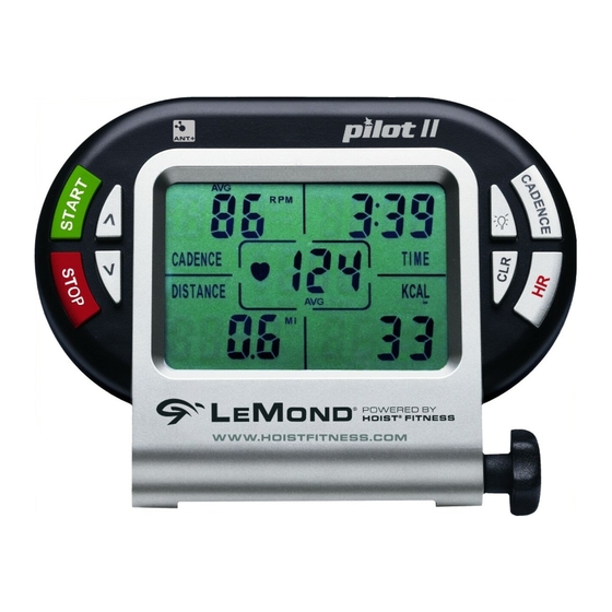
DISPALY WINDOW HEART RATE CADENCE TIME 10:30 INST CADENCE TIME KCAL DISTANCE INST CALORIES (KCAL) DISTANCE CadENCE Cadence is the measurement of how fast the crank is rotat- ing in RPM’s. The approximate speed of the bike can also be displayed (MPH/KPH) in this area. - Page 13 (BPM). Note: You must wear a chest strap during your workout in order to see your heart rate. The Pilot II console will detect heart rate signals from most chest straps that emit an analog signal and all ANT+ digital chest transmitters.
-
Page 14: Quick Start Program
qUICk START PROGRAM counting and the console will start tracking usage informa- tion. The Pilot will calculate calories burned based on the follow- ing default perimeters for Quick Start Workout: Ambient Heart Rate (AHR): 70 bpm Age: 30 Years old Weight: 175 lbs. - Page 15 CUSTOM HEART RATE TRAINING AND CALORIE CALCULATIONS Press and hold the [HR] key until the display window shows “∨ 240. ” Use the [ ∨] key to change the upper limit of your tar- get heart rate from 240 BPM to your desired beats per minute and press [HR] to select the number.
- Page 16 CUSTOM HEART RATE TRAINING AND CALORIE CALCULATIONS Use the [ ∧] or [∨] key to change the default AHR value to your AHR value. HR] key to select your AHR value. Press the [ The default age of 30 years old will be displayed. Use the [∧] or [∨] key to change the default age to your age.
-
Page 17: Key Function
kEY FUNCTIONS [sTaRT] The start key will start the timer and enable the cadence me- ter to begin calculating HR and Kcal values. [CLEaR] • A short press (< 3 sec) of the clear key will reset the time, distance and calorie measurements. •... - Page 18 ∨ The down arrow allows you to decrease the default max HR, min HR, ambient HR, age, and weight to select your values for target heart zone training and calorie calculations. [HR] • A short press of the heart rate key allows you to change the display of the HR section of the display window between INST (instantaneous) HR, AVG (average) HR and MAX (maximum) HR.
- Page 19 Pressing the light key will back-light the display window for 5 seconds. If another key is pressed while the light is on, the back light will stay on for an additional 5 seconds. As long as keys are pressed with the back light on, the console light will stay on.
-
Page 20: Cadence Training
CADENCE TRAINING definition of Cadence How rapidly the cranks are rotated or the rhythm of the ped- al stroke; often referred to as RPM (revolutions per minute). Concepts using Cadence for training You can choose the goal of your workout in relation to Resistance, Cadence, and Heart Rate . - Page 21 Resistance Used speed Change Effects on Heart Rate Light Lower RPM HR remains relaxed Light Higher RPM HR begins to rise Moderate Lower RPM HR near to steady state Moderate Higher RPM HR rises from steady state Heavy Lower RPM HR rises - hard effort Heavy Higher RPM...
-
Page 22: Troubleshooting
TROUBLESHOOTING No display on Console Press any key to bring the console out of sleep mode. Ensure that the batteries are installed properly in the console and transmitter. If they are, install fresh batter- ies. Verify that the cadence transmitter and console are paired correctly (see Appendix). - Page 23 TROUBLESHOOTING (CONT.) Cadence number jumps high or low Verify that the cadence transmitter and the console are paired to one another (see Appendix). Relocate the bike to a different part of the room, away from any RF interfernce areas. CaUTION External interference may be caused by nearby televisions, stereo equipment, speakers, electrical wire cabling, etc.
-
Page 24: Appendix
APPENDIX Notice of FCC Compliance This equipment has been tested and found to comply with the limits for a Class C Low Power Communication Device Transmitter, pursuant to Part 15 of the FCC rules. Operation is subject to the following conditions: (1) This de- vice may not cause harmful interference, and (2) this device must accept any interference received, including interference that may cause undesired operation. - Page 25 APPENDIX Pairing the Console and the Cadence Transmitter The Cadence Transmitter and the Console communicate via an ANT+ signal. They will be paired from the factory, but should they lose connection, follow the steps below to reestablish the pairing. Pairing the Cadence Transmitter (see diagram on p. 27 ) With the console ON.
- Page 26 APPENDIX Pairing to an aNT+ HR strap (see diagram on p.27) Note: HR signal detection is based on proximity; meaning whichever HR strap is the closest to the console is the signal that the console will display. If the console has trouble detecting your ANT+ HR strap, follow the steps below.
- Page 27 APPENDIX Page 27...
-
Page 28: Console Codes
APPENDIX CONsOLE COdEs [CadENCE] + [HR] Pressing both these keys switches from English units - Miles (MI), Miles per Hour (MPH), and pounds (Lb); to metric units - Kilometers (KM), kilometers per hour (KPH), and kilograms (KG) [CadENCE] + [∧] + [∨] Simultaneously pressing these three keys displays the cur- rently paired code. - Page 29 11900 Community Road Poway, CA 92064 Telephone: +1(858) 578-7676 Fax: +1(858) 578-9558 www.HOISTfitness.com Document No: 300219 Rev C © 2012 HOIST Fitness. RevMaster and Pilot are registered trade- marks of HOIST Fitness in the United States and other countries. Page 29...
Need help?
Do you have a question about the Pilot II and is the answer not in the manual?
Questions and answers