
Summary of Contents for Fibrenetix E8 Series
- Page 1 Hardware Guide E8 Series Storage Enclosure Revision 0.90 February, 2012 www.fibrenetix.com...
- Page 2 Return of Product If a distributor or Fibrenetix deems it necessary for a system to be returned for testing or servicing, a Return Materials Authorization (RMA) number will be issued. The RMA number must be placed on the outside of the carton in large, visible letters near the address label.
-
Page 3: Table Of Contents
E 8 series Hardware Guide Table of Contents Chapter 1 – Introduction ......................1 Features and Benefits ......................... 1 Understanding RAID ......................... 1 RAID 0 ............................2 RAID 1 ............................2 RAID 0+1 ..........................3 RAID 3 ............................3 RAID 5 ............................4 RAID 6 ............................ - Page 4 E 8 series Hardware Guide Figures Figure 1 RAID 0 configuration ....................2 Figure 2 RAID 1 configuration ....................2 Figure 3 RAID 0+1 configuration .................... 3 Figure 4 RAID 3 configuration ....................3 Figure 5 RAID5 configuration ....................4 Figure 6 RAID6 configuration ....................
- Page 5 E 8 series Hardware Guide Preface This User Guide describes the installation, configuration and operation of the following products: • E8-1264-F281, 12 drive bay, single controller RAID subsystem with quad 8 gigabit Fibre Channel interfaces (total 4 x 8gigabit F/C ports) •...
-
Page 6: Chapter 1 - Introduction
E 8 series Hardware Guide Chapter 1 – Introduction Thank you for purchasing your Fibrenetix E8 Series RAID enclosure. Designed for speed, reliability, compatibility and performance, the E8 enclosure is easy to install, providing an outstanding and versatile solution to meet all your data storage requirements. The User Guide presumes that you are familiar with standard computer operations including managing and organizing files and folders. -
Page 7: Raid 0
E 8 series Hardware Guide RAID 0 RAID 0, also referred to as striping, writes stripes of data across multiple disk drives. RAID 0 does not provide any data redundancy, but does offer the best high-speed data throughput. RAID 0 breaks up data into smaller blocks and then writes a block to each drive in the array. -
Page 8: Raid 0+1
E 8 series Hardware Guide RAID 0+1 Figure 3 RAID 0+1 configuration RAID 0+1 is a combination of RAID 0 and RAID 1, combining striping with disk mirroring. RAID Level 0+1 combines the fast performance of Level 0 with the data redundancy of Level 1. -
Page 9: Raid 5
E 8 series Hardware Guide RAID 5 In RAID5, the parity information is written to all of the drives in the array rather than being concentrated on a dedicated parity disk. If one drive in the array fails, the parity information can be used to reconstruct the missing data from that drive. -
Page 10: Chapter 2 - Initial Setup And Installation
Caution: Do not place or drop objects onto the enclosure and do not force any foreign objects into it. Caution: Do not expose the E8 series storage enclosures to extreme temperatures (below 5 ºC or above 40 ºC) or to direct sunlight. -
Page 11: Temperature
E 8 series Hardware Guide Temperature The operating temperature of the storage enclosure is between 5 C and 40 C. However, it is not recommended that the enclosure be continuously run at these extreme temperatures. Consideration should therefore be give to ensure that the room ambient temperature is compatible with these specifications. -
Page 12: Locating Components
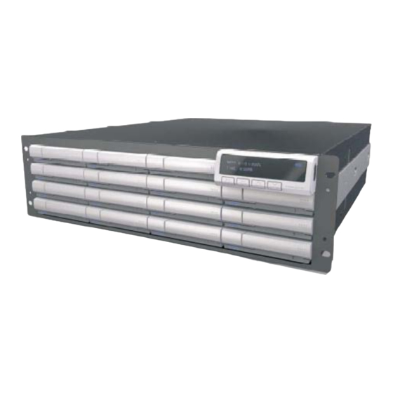
E 8 series Hardware Guide Locating Components The following picture of the E88-1664-F281 shows where the components are located within the enclosures. Front Panel Display Drive Caddies Figure 7 Front view of enclosure The above drawing shows the front view of the enclosure. The LCD panel is designed to be removable (16 bay model only). -
Page 13: Fru Removal
E 8 series Hardware Guide Figure 9 Rear view of E8 16 bay JBOD enclosure FRU removal Power and Cooling (PAC) The PAC modules can be easily removed by unscrewing the thumbscrews and pulling it outwards. RAID Controller To gain access to the RAID controller unscrew the thumbscrews in an anti-clockwise direction, lower the latch assembly and pull the controller outwards. -
Page 14: Figure 10 Drive Mounting
E 8 series Hardware Guide Figure 10 Drive mounting The drives are mounted from the underside of the drive caddy by the four screws shown above. Upgrading the memory The memory installed in the RAID controller module can be upgraded by removing the controller as described above and removing the memory by opening the securing clips. -
Page 15: Chapter 3 - Initial Configuration
E 8 series Hardware Guide Chapter 3 – Initial Configuration This Chapter describes how to install the hardware and how to connect to and access the RAID controller. Note: A maximum of 32 physical drives is allowed per RAID set. Attaching the Fibre Channel Cables to Fibre Channel enclosures There are four Fibre channel SFP Ports on the rear of the enclosure at the rear of the unit. -
Page 16: Power Sequencing Of Subsystems
E 8 series Hardware Guide Note: When adding JBOD enclosures follow the order shown in Figure 13 above. Power sequencing of subsystems Power up 1. Apply power to JBOD enclosures 2. Wait one minute to allow drives to come up to speed 3. -
Page 17: Web Browser-Based Raid Manager
E 8 series Hardware Guide By connecting a VT100 terminal, or a PC operating in an equivalent terminal emulation mode, all RAID subsystem monitoring, configuration and administration functions can be carried out. There are a wide variety of Terminal Emulation packages available, such as Hyperterm. -
Page 18: Web Browser-Based Raid Manager Via Http Proxy
Web browser-based RAID manager via HTTP Proxy The browser based RAID manager can be accessed via a HTTP Proxy. The Fibrenetix system comes with proxy software for Windows based host systems. To run the proxy software, double click on the executing file archttp.exe. The Archttp dialog box appears. -
Page 19: Figure 15 Gui Configuration Screen
E 8 series Hardware Guide To start the ArcHttp Proxy Server web-browser management, click Start. Type the User Name and Password when prompted. The RAID controller default User Name is "admin" and the Password is "0000". After entering the user name and password, press Enter to start-up the Http Proxy Server. -
Page 20: Front Panel Operation
E 8 series Hardware Guide NOTE: Alert by Email Configuration can only be set in the web- based configuration Front Panel Operation The system ( 1 6 b a y o n l y ) can also be configured from the front panel display. It is recommended that detailed configuration is performed using normal keyboard or mouse input rather than through the front panel, however the display is useful for setting up IP addresses prior to more involved configuration and reading status information. -
Page 21: Troubleshooting
E 8 series Hardware Guide Appendix A Troubleshooting Q. I have created a 2.5 TB LUN and my Operating System does not recognize the full capacity. A. Ensure that your Operating System supports volumes sizes greater than 2 TB. This is achieved by using 16 bit SCSI Command Descriptor Blocks. -
Page 22: Technical Specifications
E 8 series Hardware Guide Appendix B Technical Specifications System Max number of devices: Max number of disk drives per RAID set: Maximum number of drives per 12/16 enclosure Supported RAID levels: JBOD, 0, 1, 0+1, 3, 5, 6, 30, 50, 60 Host Bus Interface: Quad 8GBit Fibre Channel Maximum controller cache...
Need help?
Do you have a question about the E8 Series and is the answer not in the manual?
Questions and answers