
Related Manuals for SCI ERV-24-HC11

Summary of Contents for SCI ERV-24-HC11
-
Page 1: Technician Settings
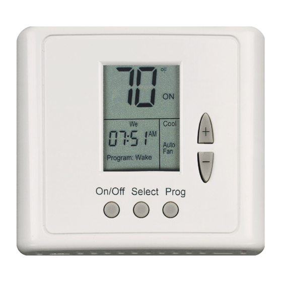
ERV-24-HC11 ® With FanCycler Technician Settings Pipersville, PA 18947 USA Cat. P048013 Phone: 215-766 1487 - Fax: 215-766 1493 Rev. 2.1 12.04 Email: support@scillc.com - www.scillc.com... -
Page 2: Table Of Contents
Please read this manual carefully before installation and use. Index Introduction Options and Accessories Installation Instructions Wiring connections DIP Switch and Jumpers explanation Remote Sensor connections Advanced Setup Fan Cycling Configuration Ventilation Damper Cycling Fan over-run after cooling status Fan cycling at night in heating mode status Circulator pump status Data Storage for System Diagnostics Locking the thermostat’s buttons... -
Page 3: Introduction
1. Introduction ® Advanced Ventilation Features of the ERV-24-HC11 thermostat with FanCycler Protected by one or more of the following patents: US 5,547,017; 5,881,806; 6,431,268; CA 2,245,135 ® The ERV-24-HC11 thermostat with FanCycler has enhanced features to compliment controlled mechanical ventilation systems. These features were configured for use by your installing technician. -
Page 4: Options And Accessories
RS02: for averaging temperature at 2 locations (2 required) – the thermostat will control on the average temperature of both locations For details on where to purchase accessories, please contact SCI for your nearest location or visit our web site at www.scillc.com 3. -
Page 5: Wiring Connections
(the designated terminals on the printed circuit board are for internal (factory) use only). “T” Terminals can be used in any system configuration when a SCI remote sensor is connected and the DIP switch is correctly configured. - Page 6 The Rc/Rh terminals are bridged at the factory for a one transformer application. In the case of a two transformer application, you must remove the bridge and connect the individual transformers to Rc (cool) and Rh (heat). FD – Fresh-Air Damper connection - 24Vac/1Amp. The damper type must be Power Open, Spring Close.
- Page 7 Table 5.1 – DIP switch selection DIP Switch settings FUNCTION Internal temp. sensor Remote temp. sensor Electric Oil/Gas 3 min. compressor delay No compressor delay Programmable Non-Programmable x = Disregard = Factory Defaults = FOR TEST ONLY 5.2 DIP Switch Operation •...
- Page 8 5.4 Jumpers explanation Jumper 1: Complete Reset of the unit. For complete reset: • Move JMP1 to position B. • Wait 15 seconds. • Return JMP1 to position A. JMP1 Default from factory: Jumper 2: NOT IN USE. JMP2 Default from factory: Leave it closed! Jumper 10: Enable or disable Auto change-over capability •...
-
Page 9: Remote Sensor Connections
6. Remote temperature sensor connections – (optional) Important! The remote temperature sensor must be SCI type. Table 6.1 - N.TC. Sensor: Temperature ~ Resistance Characteristics Temp °C 10.0 12.8 15.6 18.3 21.1 23.9 26.7 29.4 32.2 Temp °F Res. k 115.8... - Page 10 6.1.2 Remote sensor wiring configurations Connection of one remote sensor (RS01) mount in acceptable RS01 THERMOSTAT location for temperature sensor Connection of two remote sensors for average measuring (2XRS02) mount in acceptable RS02 location for THERMOSTAT temperature sensor RS02...
-
Page 11: Advanced Setup
7. Advanced Setup ® The ERV-24-HC11 thermostat with FanCycler has enhanced features to compliment controlled mechanical ventilation systems and combination space and domestic hot water heating systems. Follow the steps below to set the unit’s advanced features: 7.1 Enter the Advanced Setup screens of the thermostat Press and hold (4 seconds) the On/Off button to turn the thermostat OFF. -
Page 12: Fan Cycling Configuration
8. Fan Cycling Configuration The purpose of fan cycling is to assure that the central air handler fan will run enough to distribute ventilation air and evenly mix air throughout the house, even when there is no demand for heating or cooling. - Page 13 8.1 Set the fan cycling ON time and OFF time. Press and hold the Select button until “LI” or ”UnLI” or ”CALC” appears on display. Using the “+” and “-“ buttons select between: • “LI” – Fan cycling limited - default. If “LI”...
- Page 14 Press the Select button again – four digits will appear on display. Using the “+” and “-“ buttons adjust the fan cycling limited ON time. The number represents the number of minutes the fan will be energized after no fan activity for the fan OFF time. A value of 0 disables this option.
- Page 15 8.2 Set the fan duty cycle percentage and the total period. Select “Calc” in 8.1.b Press the Select button once - “Fd” will appear on display. Using the “+” and “-“ buttons adjust the fan duty cycle. The Number is the percent of time fan will be energized during each total period (will be set later –...
-
Page 16: Ventilation Damper Cycling
9. Ventilation Damper Cycling The purpose of cycling the ventilation damper is to limit the possibility of over-ventilating, which could cause unnecessary space conditioning energy to be used. The damper will open when the fan comes on, but if the fan stays on longer than needed for the introduction of ventilation air, the damper will automatically close;... -
Page 17: Fan Over-Run After Cooling Status
9.2 Set the damper cycling CLOSE time (“dC”). Press the Select button until “dC” appears on display. Using the “+” and “-“ buttons adjust the damper cycling CLOSE time. The number is the minutes the ventilation damper will be closed after the damper had been open and the fan is still operating for any reason. -
Page 18: Fan Cycling At Night In Heating Mode Status
11. Fan cycling at night in heating mode status (“Fn”) Depending on the duct system design and the occupants, it may be desirable to not allow fan cycling at night during the heating season. If this option is turned OFF fan cycling will be disabled between the hours of 9 pm and 8 am while the thermostat system mode is HEAT. - Page 19 12. Pump cycling for combination space and domestic hot water heating systems (“FE”) As building enclosures become more energy efficient and heating loads are small, a single hot water heater can often supply hot water for both domestic use and space heating. This type of heating system is especially popular in multi-family housing.
-
Page 20: Data Storage For System Diagnostics
13. Data Storage for System Diagnostics The following data is stored by the thermostat to allow advanced system diagnostics: • Average cooling set-point while cooling is active (“SC”) • Average heating set-point while heating is active (“SH”) • Average number of cooling cycles per day while in cooling mode (“CC”) •... - Page 21 To clear the average values follow these steps: Press and hold (6 seconds) the On/Off button to set the system mode to OFF Using the “+” and “-“ buttons set the temperature set-point to 90°F. When the display stops flashing, press and hold (8 seconds) the Select button until “Unlo”...
- Page 22 15. Offset Settings The Offset is used for field calibration of the measured temperature if necessary. • Press and hold (6 seconds) the On/Off button to turn the thermostat OFF. • Using the “+” and “-“ buttons set the temperature set-point to 60°F, and wait until the display stops flashing.
-
Page 23: Troubleshooting For Technician
16. Troubleshooting for Technician Problem Solution Check the thermostat for 24 VAC, remove the front cover and test between Rc/Rh to C. Check for good wiring connections at: The display is blank Rh (24 VAC for heat), Rc (24 VAC for cool), C (common). If you are using one transformer for cool and heat, check that the jumper is installed between Rc and Rh. - Page 24 SCI - Systems Controls & Instruments can offer a WIDE range of products for the HVAC industry, Such as: • Flush Mount Thermostats - Programmable and Non-Programmable. • HVAC Analyzer that can measure BTU’s, for technicians. • Tamper proof thermostats that can be operated ONLY from the remote control, for public places.
Need help?
Do you have a question about the ERV-24-HC11 and is the answer not in the manual?
Questions and answers