Advertisement
Quick Links
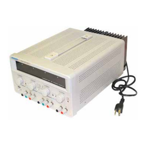
User Manual of
Precision AC- DC Power Supply: Dual Channel 0-30V ,
5A max or 0-60V single channel
AA Portable Power Corp (http://www.batteryspace.com)
th
Address: 860 S, 19
St, Unit A, Richmond, CA, 94804
Tel: 510-525-2328
Fax: 510-439-2808
Email: Sales@batteryspace.com
Prepared & Approved by Max (20/10/10)
Advertisement

Related Manuals for AA Portable Power Corp Precision AC- DC Power Supply

Summary of Contents for AA Portable Power Corp Precision AC- DC Power Supply
- Page 1 User Manual of Precision AC- DC Power Supply: Dual Channel 0-30V , 5A max or 0-60V single channel AA Portable Power Corp (http://www.batteryspace.com) Address: 860 S, 19 St, Unit A, Richmond, CA, 94804 Tel: 510-525-2328 Fax: 510-439-2808 Email: Sales@batteryspace.com Prepared & Approved by Max (20/10/10)
- Page 2 1. INTRODUCTION Adjustable DC power supply are designed to be used in applications such as powering operational amplifier, push pull stages, logic circuit and definition systems where plus and minus voltages are required to track with an insignificant error, and in any application where three independent power supplies housed in a single package represent an operating convenience.
- Page 3 TRACKING switches. B. Because both voltage and current of the SLAVE supply track the MASTER supply, the maximum current and voltage are set using the MASTER controls. Using the MASTER supply output jacks, follow the instructions for "Setting Current Limit" (4-2 Section). Remember that the actual current output at the MATER supply output jack is double the reading on the SLAVE indicator meter.
-
Page 4: Power Supply
If the chassis or common of the equipment being powered is separate from both positive and negative polarity power inputs. The output of the SLAVE (negative) supply is tracking the output of the MASTER (positive) supply. The configuration is shown in MAST ER LOAD SLAVE... - Page 5 Rating Model Specifications 2H 0~30V Output voltage 2H 0~30V 2H 0~30V 2H 0~30V 2H 0~5A Output current 2H 0~3A 2H 0~5A 2H 0~3A Output fixed 5V,3A 5V,3A 5V,3A 5V,3A Output on/off V/A initializes Dimensions: 245(W)H140(H)H345(D)mm Weight: Approx.8kg 2-2 Operation Mode (1).
- Page 6 When the series tracking mode of operation is selected, the positive (red) terminal of the SLAVE supply output is internally connected to the negative (black) terminal of the MASTER supply. In the series tracking mode, the maximum output voltage of both MASTER and SLAVE supplies can be simultaneously varied with one control.
- Page 7 supply is in the INDEPENDENT operating mode. B. Adjust "Voltage" control and "Current" control to the desired output voltage and current. C. Turn off the power supply and the equipment to be powered during hook-up. D. Connect the positive polarity of the device being powered to the red (+) terminal of the power supply.
-
Page 8: Panel Controls And Indicators
Between chassis and AC cord 300MW or above (DC 500V) 3. PANEL CONTROLS AND INDICATORS Fig.3-1 F ront Panel... - Page 9 VO M AX IO MAX Cons tant Current Range Crosso ver Point Cons tant Voltage Output Range Voltage Out put Cu rrent Fig.4-1 Con st ant Volt age/Co ns tant Character is tic. (3). Output voltage overshoot Maybe voltage between output terminals exceeds the present value when the power is turned on or off.
- Page 10 mode, a regulated output voltage is provided. The output voltage remains constant as the load increases up until the point where the preset current limit is reached. At that point, the output current becomes constant and the output voltage drops in proportion to further increases in load. The point is indicated by the front panel LED indicators.
- Page 11 In this mode, maximum voltage of both supplies is set using the MASTER VOLTAGE controls (voltage at output terminals of the SLAVE supply tracks the voltage at the output terminals of the MASTER supply). Also, in this mode of operation the positive terminal (red) of the SLAVE supply is connected to the negative terminal (black) of the MASTER supply.
- Page 12 Fig .3-2 Rear Panel...
Need help?
Do you have a question about the Precision AC- DC Power Supply and is the answer not in the manual?
Questions and answers