Table of Contents
Advertisement
Quick Links
INSTALLER'S MANUAL
CLEAN BURN MODEL: DOUBLE-PISTON AIR COMPRESSOR #14336
Optional Accessories for Clean Burn Furnaces/Boilers
I89056
PUBLICATION DATE: 1/4/10, Rev. 5
CLEAN BURN PART # 43142
IMPORTANT FOR U.S. INSTALLATIONS: All installations must be made in accordance with state and local codes which
may differ from the information provided in this manual. Save these instructions for reference.
IMPORTANT FOR CANADIAN INSTALLATIONS: The installation of this equipment is to be accomplished by qualified
personnel and in accordance with the regulation of authorities having jurisdiction and CSA Standard B 139, Installation
Code for Oil Burning Equipment.
Advertisement
Table of Contents

Summary of Contents for Cleanburn 14336
- Page 1 INSTALLER'S MANUAL CLEAN BURN MODEL: DOUBLE-PISTON AIR COMPRESSOR #14336 Optional Accessories for Clean Burn Furnaces/Boilers I89056 PUBLICATION DATE: 1/4/10, Rev. 5 CLEAN BURN PART # 43142 IMPORTANT FOR U.S. INSTALLATIONS: All installations must be made in accordance with state and local codes which may differ from the information provided in this manual.
- Page 3 WARRANTY INFORMATION Clean Burn, Inc., MANUFACTURER, hereby warrants that MANUFACTURER's products shall be free from defect in material and workmanship under normal use according to the provisions and limitations herein set forth. MANUFACTURER warrants the heat exchanger/combustion chamber for a period of ten (10) years (or 15,000 hours, whichever comes first), from the date of purchase by the purchaser, as follows: If the defect occurs in the first five (5) years (or 7500 hours, whichever comes first) , Clean Burn pays 100% of parts, replacement or repair (the customer pays 0%), and pro rata thereafter according to the following schedule:...
- Page 4 TRADEMARKS The Clean Burn logo is a trademark of Clean Burn, Inc. All other brand or product names mentioned are the registered trademarks or trademarks of their respective owners. COPYRIGHT Copyright © 2010 Clean Burn, Inc. All rights reserved. No part of this publication may be reproduced, or distributed without the prior written permission of Clean Burn, Inc.
-
Page 5: Table Of Contents
TABLE OF CONTENTS NOTE: A Special Bulletin (which appears just after the Table of Contents) has been added to your manual to highlight important information about the installation, adjustment and operation of your air compressor. Be sure to read this sheet before beginning any procedures in this manual. -
Page 7: Air Compressor Model
IMPORTANT INFORMATION CONCERNING THE SERVICE RATING OF THE AIR COMPRESSOR Air compressor model #14336 has a service rating of approximately 75%. This means that the air compressor can operate continuously for approximately 45 minutes (75% of one hour), and then it must not operate for approximately 15 minutes (25% of one hour) to allow the air compressor to "cool down."... -
Page 9: Section 1: Introduction
Installer's Manual: Clean Burn Air Compressors SECTION 1: INTRODUCTION Guide to this Manual IMPORTANT! This manual provides all the instructions necessary to install the Clean Burn air compressor on your Clean Burn furnace or boiler. Refer to your equipment Operator's Manual for instructions on assembling, installing, operating, and maintaining your furnace or boiler. -
Page 10: For Your Safety
Installer's Manual: Clean Burn Air Compressors Please read all sections in this manual carefully--including the following safety information--before beginning any installation procedures; doing so ensures your safety and the optimal performance of your Clean Burn air compressor and furnace/boiler. For Your Safety... For your safety, Clean Burn documentation contains the WARNING! following types of safety statements (listed here in order... -
Page 11: Section 2: Unpacking
Installer's Manual: Clean Burn Air Compressors SECTION 2: UNPACKING Before installing the air compressor on your furnace/boiler, you should take some time to carefully unpack your shipment from Clean Burn. Unpacking and Inspecting All Components Carefully open all shipping containers and inspect all components. Immediately notify the freight company and your Clean Burn dealer in case of shipping damage or shortage(s). - Page 12 Installer's Manual: Clean Burn Air Compressors...
-
Page 13: Section 3: Installing The Air Compressor
Installer's Manual: Clean Burn Air Compressors SECTION 3: INSTALLING THE AIR COMPRESSOR IMPORTANT! If you are installing your furnace/boiler and air compressor at the same time, Clean Burn recommends the following sequence of activities: 1. Assembly of Furnace/Boiler (for furnace - through the installation of mounting/stabilizer brackets). 2. - Page 14 Installer's Manual: Clean Burn Air Compressors I89055 Figure 3A - Air Compressor Exploded View...
-
Page 15: Installing The Air Compressor Components
Installer's Manual: Clean Burn Air Compressors ITEM QTY PART# DESCRIPTION 32280 1/8" ELBOW 90° 32234 HOSE BARB (3/8" H x 1/8"NPT) 54063 AIR HOSE (3/8",42" LONG) 32236 HOSE BARB(3/8"H x 1/4" NPT) 32233 BRASS STREET TEE (1/4" NPT) 32146 RELIEF VALVE 32091 HOSE CLAMP 13063... - Page 16 Installer's Manual: Clean Burn Air Compressors I89060 Figure 3B - Air Compressor Installed on the Saturn 140 / Saturn 240...
-
Page 17: Preparing The Furnace Cabinet (Saturn 140 / Saturn 240)
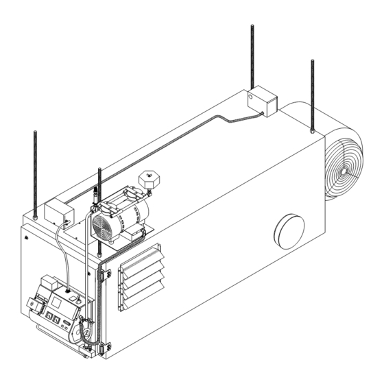
Installer's Manual: Clean Burn Air Compressors Preparing the Furnace Cabinet (Furnace Models Saturn 140 / 240) Refer to Figures 3A and 3B. Install all-thread rods through the mounting holes in the base and top of the furnace cabinet. Use double nuts to securely lock the all-thread rods in position. - Page 18 Installer's Manual: Clean Burn Air Compressors I89056 Figure 3C - Air Compressor Installed on the CB-1750 / CB-2500 / CB-3250...
- Page 19 Installer's Manual: Clean Burn Air Compressors Preparing the Furnace Cabinet (Furnace Models CB-1750/2500/3250) Refer to Figures 3A and 3C. Install all-thread rods in the mounting lugs on top of the furnace cabinet. Use double nuts to securely lock the all-thread rods in position. Mounting the Air Compressor (Furnace Models CB-1750/2500/3250) CAUTION: The compressor must be securely mounted as described in this section.
- Page 20 Installer's Manual: Clean Burn Air Compressors I89058 Figure 3D - Air Compressor Installed on the CB-3500 / CB-5000...
-
Page 21: Mounting The Air Compressor (Saturn 140 / Saturn 240)
Installer's Manual: Clean Burn Air Compressors Preparing the Furnace Cabinet (Furnace Models CB-3500 and CB-5000) Refer to Figures 3A/3D and your Furnace Operator's Manual for an overview of furnace assembly (refer specifically to information on the installation of the mounting/stabilizer brackets and the all-thread rods). -
Page 22: Preparing The Cb-500 Series Burner For Use With The Air Compressor
CB-500 series burner for use with the air compressor assembly #14336. Remove the self-tapping screw with a 1/4" nut driver and swing open the double-hinged lid to expose the heater block assembly. - Page 23 Installer's Manual: Clean Burn Air Compressors Preparing the CB-500 Series Burner for use with the Air Compressor (continued) LOCKING BAR SAVE AND USE THESE 4 SCREWS AND WASHERS TO INSTALL SQUARE CAP STEP 1 SURFACE MOUNTED REMOVE AIR REGULATOR THESE PARTS (COMPLETE REGULATOR) STEP 2...
-
Page 24: Connecting The Air Compressor To The Cb-500 Series Burner
Installer's Manual: Clean Burn Air Compressors Connecting the Air Compressor to the CB-500 Series Burner IMPORTANT: Run the 3/8" air hose directly from the air compressor to the burner. Do not use the connector block. Refer to Figure 3G. Remove the female elbow 1/4" tube push fitting from the air pressure inlet port on the burner. Install the supplied 1/8"... -
Page 25: Preparing The Saturn Burner For Use With The Air Compressor
Figure 3H shows an exterior view of the Saturn burner components. In this procedure, you will be removing the internal air regulator components to prepare the Saturn burner for use with the air compressor assembly #14336. Remove the self-tapping screws with a 1/4" nut driver and open the electrical box cover to expose the air regulator assembly. -
Page 26: Connecting The Air Compressor To The Saturn Burner
Installer's Manual: Clean Burn Air Compressors ITEM # PART# DESCRIPTION 32221 POPPET SPRING 32222 POPPET VALVE 32223 POPPET O−RING 32305 BRASS SEAT 32225 DIAPHRAM 32226 DIAPHRAM RING 33308 BONNET 34145 3/4" PANEL NUT 32202 1/4T PUSH X 1/8 NPT FEM ELBOW REMOVE I89063 Figure 3I - Removing the Air Regulator Components on the Saturn Burner... -
Page 27: Section 4: Operating & Maintaining The Air Compressor
Installer's Manual: Clean Burn Air Compressors SECTION 4: OPERATING & MAINTAINING THE AIR COMPRESSOR Adjusting the Air Compressor During Operation It is very important to adjust the pressure relief on the air compressor to provide the burner with the precise air pressure (12 to 18 psi) required for proper burner opera- tion. -
Page 28: Maintaining The Air Compressor
Installer's Manual: Clean Burn Air Compressors Maintaining the Air Compressor ATTENTION: Never introduce oil into the head of the air compressor. Oil will damage the teflon seals of the air compressor and will void your warranty. Clean the air intake filter element at least monthly according to the manufacturer's instructions included with the filter. -
Page 29: Technical Reference Materials
Installer's Manual: Clean Burn Air Compressors APPENDIX A Technical Reference Materials FIGURE A1 - Burner Wiring Schematic (Similar for all CB-500 Series burners) - Page 30 Installer's Manual: Clean Burn Air Compressors FIGURE A2 - Saturn Burner Wiring Schematic...
-
Page 31: Air Compressor Wiring
Installer's Manual: Clean Burn Air Compressors DOUBLE PISTON AIR COMPRESSOR WIRING ORANGE WIRENUTS BLUE WHITE WHITE BLUE FLEX CONDUIT BROWN CONNECT ONE END OF THE GROUND WIRE TO THE GROUND SCREW ON THE COMPRESSOR CAPACITOR AND THE OTHER END TO THE SCREW ON THE OUTSIDE OF THE JUNCTION BOX TO TERMINAL BLOCK INSIDE I88533−A... - Page 32 Installer's Manual: Clean Burn Air Compressors...
Need help?
Do you have a question about the 14336 and is the answer not in the manual?
Questions and answers