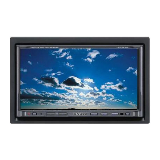
Kenwood DDX6029 Installation Manual
Monitor with dvd receiver
Hide thumbs
Also See for DDX6029:
- Instruction manual (84 pages) ,
- Installation manual (73 pages) ,
- Service manual (87 pages)
Advertisement
DDX6029
MONITOR WITH DVD RECEIVER
INSTALLATION MANUAL
MONITEUR AVEC RÉCEPTEUR DVD
MANUEL D'INSTALLATION
MONITOR MIT DVD-RECEIVER
INSTALLATION-HANDBUCH
MONITOR MET DVD-ONTVANGER
INSTALLATIE HANDLEIDING
MONITOR CON RICEVITORE DVD
MANUALE DI INSTALLAZIONE
MONITOR CON RECEPTOR DVD
MANUAL DE INSTALACION
MONITOR COM RECEPTOR DVD
MANUAL DE INSTALAÇAO
© B54-4493-00/00 (EV)
Advertisement
Table of Contents

Summary of Contents for Kenwood DDX6029
-
Page 1: Installation Manual
DDX6029 MONITOR WITH DVD RECEIVER INSTALLATION MANUAL MONITEUR AVEC RÉCEPTEUR DVD MANUEL D'INSTALLATION MONITOR MIT DVD-RECEIVER INSTALLATION-HANDBUCH MONITOR MET DVD-ONTVANGER INSTALLATIE HANDLEIDING MONITOR CON RICEVITORE DVD MANUALE DI INSTALLAZIONE MONITOR CON RECEPTOR DVD MANUAL DE INSTALACION MONITOR COM RECEPTOR DVD MANUAL DE INSTALAÇAO... - Page 2 Accessories ..1 ..1 ..1 ..1 ..1 ..2 ..1 English...
-
Page 3: Installation Procedure
Installation Procedure 1. To prevent short circuits, remove the key from the 2CAUTION ignition and disconnect the - terminal of the • If the power is not turned ON (or it is ON, but battery. will be OFF immediately), the speaker wire may 2. - Page 4 Connection Connection cable (Included in the disc changer) Disc Changer etc.(Optional) Accessory 4 FM/AM antenna input Antenna Cord Connect to the vehicle's parking brake detection switch harness TV tuner (Optional) using the supplied relay connector. For the sake of safety, be sure to connect the parking sensor. Parking sensor wire PRK SW Reveres sensor wire...
-
Page 5: Navigation System (Optional)
Mute wire (Brown) Connect to the terminal that is grounded when either the telephone rings or during conversation. MUTE To connect the Kenwood navigation system, consult your navigation manual. External amplifier control wire (Pink/Black) To "EXT.AMP.CONT. " terminal of the amplifier having EXT.CONT... - Page 6 Connecting the ISO Connector The pin arrangement for the ISO connectors depends on the type of vehicle you drive. Make sure to make the proper connections to prevent damage to the unit. The default connection for the wiring harness is described in 1 below. If the ISO connector pins are set as described in 2 or 3, make the connection as illustrated.
-
Page 7: System Connection
System Connection Do not connect. Cooling fan To Navigation System ■ Rear View Camera Input • Visual input (Yellow) ■ Audio/Visual Output • Visual output (Yellow) ■ Audio/Visual input • Visual input (Yellow) • Audio left input (White) • Audio right input (Red) ■... -
Page 8: Installing The Escutcheon
Installing the Escutcheon ■ For General Motors 1. Refer to the section <Removing the Hard Cut out to meet the shape of the Rubber Frame> and then remove the hard opening in the vehicle. rubber frame. 2. Cut out accessory 5 to meet the shape of the opening of the center console. - Page 9 ■ For Nissan 1. Refer to the section <Removing the Hard Rubber Frame> and then remove the hard rubber frame. 2. Attach accessory 7 to the unit. Accessory 7 English...
- Page 10 Installation for Monitor/Player Unit Firewall or metal support Screw (M4X8) (commercially available) Bend the tabs of the mounting sleeve with a screwdriver or similar utensil and attach it in place. Accessory 2 Self-tapping screw Metal mounting strap (commercially available) (commercially available) Make sure that the unit is installed securely in place.
-
Page 11: Removing The Unit
Removing Monitor/Player Unit ■ Removing the Hard Rubber Frame (escutcheon) 1. Engage the catch pins on the removal tool 3 Removal Tool (Accessory 3) and remove the two locks on the lower level. Lower the frame and pull it forward as shown in the figure.


Need help?
Do you have a question about the DDX6029 and is the answer not in the manual?
Questions and answers