Table of Contents
Advertisement
Advertisement
Table of Contents

Related Manuals for Drew Technologies DashDAQ XL

Summary of Contents for Drew Technologies DashDAQ XL
- Page 1 DashDAQ XL Instruction Manual...
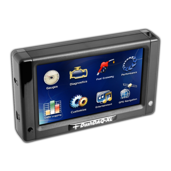
- Page 2 The DashDAQ XL works with any OBDII vehicle. It can also be fitted to any other vehicle using optional add-ons. Now you have a device that captures information on your new vehicle as well as your vintage one.
-
Page 3: Table Of Contents
Table Of Contents Installation..........................9 SAFETY FIRST! ............................9 OBDII Connector............................. 9 Cable Routing ............................9 Attaching Windshield Mount ....................... 10 Windshield Mounting........................... 10 Connections............................11 SD Memory Card ..........................12 Basic Operation ........................12 Off / On / Low Power Mode......................... 12 Menu Navigation.......................... - Page 4 Warning Sounds ........................... 21 Media PLayer............................22 Setting Signal/Graph Colors ......................... 22 Data Logging............................23 Global Data Logger ..........................24 Diagnostic Code Reader ......................25 Performance Measurements ....................26 1/4-mile, 1/8-mile, 0-60mph Test......................26 User Defined Speed Tests ........................27 Calculators ..........................
- Page 5 Using Device Manager.......................... 38 Adding support for Enhanced OBD2 DATA ..................39 Adjusting Driver Parameters ........................ 40 Updating DashDAQ ........................ 41 Install the DashDAQ Recovery Tool ..................... 41 Updating DashDAQ ..........................43 APPENDIX ..........................49 Support 49 Technical Specifications ........................49 Limited Warranty ..........................
- Page 6 Components Included with DashDAQ DashDAQ XL Software CD Windshield Mount with four screws USB Cable OBD2 Cable...
- Page 7 Optional DashDAQ Accessories DashDAQ Accessory Cable SD Memory Card. 110 V Power Supply 10-pin accessory cable for analog and For data logging on DashDAQ. Order the Power the DashDAQ outside of your in serial connection. Allows for up to two 0- SD Memory card directly from Drew the comfort of your home or office.
- Page 8 BUYER has read and understands this agreement and accepts its terms and conditions. This agreement takes precedence. DISCLAIMER OF LIABILITY Drew Technologies and its successors, distributors, jobbers, and dealers (hereafter SELLER) shall in no way be responsible for the product’s proper use and serviceability. THE BUYER HEREBY WAIVES ALL LIABILITY CLAIMS.
-
Page 9: Installation
INSTALLATION SAFETY FIRST! Install DashDAQ in such a manner that it does not interfere with the safe operation of the vehicle. If DashDAQ cannot be mounted in such a manner, promptly return the DashDAQ, in new and unused condition, with a dated proof of purchase, to the place of purchase for a full refund less a 20% restocking fee. -
Page 10: Attaching Windshield Mount
ATTACHING WINDSHIELD MOUNT 1. Remove these two items from packaging: Display Unit b. Windshield Mount 2. Line up the four holes on the windshield mount and thread each of the four screws into the display unit. 3. Using a Phillips head screwdriver, lightly tighten each of the four screws. Note: Over-tightening can possibly damage DashDAQ. Tighten the screws so they are snug, no more. -
Page 11: Connections
CONNECTIONS Audio Output 10-Pin Accessory Port 8-Pin OBDII Port USB Update Port WARNING: Do not power DashDAQ from the PC with the USB ports on the right. Permanent damage to your DashDAQ can occur. USB Ports Power Button MMC SD Memory Card Slot Light Sensor... -
Page 12: Sd Memory Card
To agree and continue, tap the [I Accept] button. If you do not agree to abide by the warning, please disconnect DashDAQ and contact Drew Technologies for a return authorization. Tapping the [I Accept] button will bring up the gauge screen:... - Page 13 The [<<] and [>>] arrow buttons at the bottom are used to cycle through different gauge layouts. The [Exit] button in the lower left corner returns the screen to the main menu for accessing all of DashDAQ’s features.
-
Page 14: Main Menu
MAIN MENU... -
Page 15: Setup Menu Map
SETUP MENU MAP... -
Page 16: New Vehicle Setup
NEW VEHICLE SETUP The DashDAQ was designed to be used on any OBDII vehicle. OBDII vehicles have many “signals” or “parameters” that can be viewed. Each vehicle to which the DashDAQ is connected will have a different set of parameters or signals available. Run the Find Signals function every time the DashDAQ is plugged into a different vehicle. -
Page 17: Custom Splash Screen
Figure 2: DashDAQ main menu with GPS option If your GPS kit is purchased separately: 1. When ordering the GPS-NAV-KIT at DashDAQ.com or through any other vendor, make sure you send the serial number of your unit with the order ticket. This is how your unit becomes licensed for the GPS software. 2. -
Page 18: Dashdaq Media Player
DASHDAQ MEDIA PLAYER The DashDAQ XL has the ability to play various sound and video files. This is done through an add-on called Media Player. The Media Player is not installed on DashDAQ when it is shipped. This add-on is free and can be installed by updating DashDAQ with the DashDAQ Recovery Tool (See Section “Updating DashDAQ”... -
Page 19: Gauge Setup & Navigation
GAUGE SETUP & NAVIGATION NAVIGATING GAUGES: Tap on [Gauges] from the Main Menu. The last gauge layout viewed, or this screen, will be displayed. Figure 3: Layout with 3 round gauges To change gauge layouts, tap on the [<<] and [>>] buttons. Two gauge layout examples: Figure 4: Layout for graphing up to 8 signals Figure 5: Layout for displaying up to 9 numeric signals ASSIGN A SIGNAL TO A GAUGE... -
Page 20: Set Gauge Min/Max Values
Figure 6: Assign signal screen SET GAUGE MIN/MAX VALUES Tap on the [Minimum] button to set the bottom value for a gauge. Tap on the [Maximum] button to set the top value of the gauge. 1. Tap [Maximum] will bring up this screen: 2. -
Page 21: Warning Sounds
Figure 8: Round gauge with a high limit warning WARNING SOUNDS DashDAQ has the ability to play either one of the pre-made or user made warning sounds when a specific parameter has gone above or below a user specified range. Besides using the pre-packaged sounds, DashDAQ users can also create and use their own warning sounds on DashDAQ. -
Page 22: Media Player
To upload your own sounds: 1. Sound files must have these attributes: Extension: .wav Encoding: PCM (uncompressed) Size: 8 or 16 bit signed integer Sample Rate: 22050, 11025, 5512 or 5513 KHZ Channels: Stereo or Mono Length: Less than 10 seconds 2. -
Page 23: Data Logging
Figure 10: Button to change gauge color Figure 11: Color selection screen DATA LOGGING The DashDAQ can log and save all information represented on the gauges. The information can saved as a Microsoft Excel *.csv, or Logworks *.dif file directly to a inserted SD memory card. To begin data logging: 1. -
Page 24: Global Data Logger
Figure 13: Entering the logfile prefix Now all log files will be saved in numerical order with the prefix that was entered. Example: TestDrag0000.csv. To view log files: 1. Remove the SD memory card from the DashDAQ. 2. Place the memory card into a SD card reader and attach to your PC. 3. -
Page 25: Diagnostic Code Reader
Figure 14: Global Data Logging Screen Figure 15: After adding a signal for global datalogging The signals specified in the Global Data Logger (up to 16) will be logged alongside what is specified in the gauge layout that the user is currently logging from. -
Page 26: Performance Measurements
Figure 17: Confirmation to clear diagnostic trouble codes Note: Clearing codes does not solve any underlying vehicle issues. Tap [Yes] to clear the code(s) and turn the check engine light off. Tap [No] to leave the code(s) set and leave the check engine light on. PERFORMANCE MEASUREMENTS 1/4-mile, 1/8-mile, 0-60mph times and many configurable performance tests can be measured with DashDAQ. -
Page 27: User Defined Speed Tests
Figure 20: Follow the instructions Figure 21: DashDAQ will display your reaction time and other measurements Tap [Start] to start the test. Follow the on-screen instructions. The results will be posted in the left box at the end of the run. Example: USER DEFINED SPEED TESTS Create your own performance tests. -
Page 28: Calculators
Tap [Save]. Make sure the speed gauge is set (section 0) and tap [save] once more. At the performance menu, tap on [User Tests]. This screen appears: Tap on [User Test 1]. Tap [Start] to start User 1’s test. Follow the on-screen instructions. The results will be posted on-screen at the end of the run. Example of a results screen: CALCULATORS DashDAQ can calculate values for horsepower, fuel economy, or even subtract two signals. -
Page 29: Setting The Parameters For Any Calculator Driver
SETTING THE PARAMETERS FOR ANY CALCULATOR DRIVER Some calculators have some tunable parameters like: vehicle weight, fuel density, or engine displacement. Others may require you to choose a signal for Vehicle Speed or Engine RPM. All of these decisions are ultimately your decision. You might specify Engine RPM from GenericOBD2 connector but use a Vehicle Speed from a GPS for higher accuracy. -
Page 30: Fuel Economy Calculator
Figure 27: Parameters for dyno calculator Only three parameters are required for the calculation: Input Speed Signal: Choose Vehicle Speed from GenericOBD2 • Input RPM Signal: Choose Engine RPM from GenericOBD2 • Input Vehicle Weight (lbs): Enter the vehicle weight in pounds •... -
Page 31: Rescale Signal Calculator
Figure 28: Parameters for Economy Calculator This calculator uses airflow to find the amount of fuel entering the motor. Vehicles with a Mass Airflow Sensor can measure airflow directly. In this case you’d only need to configure four parameters: Air Fuel Ratio: 14.7 for gasoline •... - Page 32 The calculation is based on signals, so if you want to multiply/offset by a constant number you’ll need to create a signal with that constant number. Fortunately this driver has two parameters that can generate signals with a constant value: Constant Multiplier: Used to generate a signal called “Constant Multiplier”.
-
Page 33: Statistics Calculator (Min / Max / Average)
EXAMPLE: ADJUSTING VEHICLE SPEED FOR TIRE SIZE Imagine that you changed tires from 185/60-14 to 195/55-14 and now the speedometer is incorrect because you haven’t reprogrammed the ECM. The internet says that there would be a -1.3% difference and you want to compensate for that on the speed gauge. -
Page 34: Connections And Wiring
There are two drivers included with DashDAQ, the Linear Analog driver (Analog Input) and Non Linear Analog Driver (Non Linear Analog Input). The Linear Driver is for measuring signals that have a constant input voltage change for a given change in what’s being measured. An example is a sensor that has a 0.1V output change for every temperature degree it’s measuring. -
Page 35: Converting An Analog Voltage Into Physical Units
This procedure will help you find values for Correction Factor and Correction Offset. The LC1-1’s instruction manual says that its 0-5v analog output represents AFR=7.35 to AFR=22.39. With that information you can setup two equations: Correction Factor * 0v DC + Correction Offset = 7.35 Correction Factor * 5v DC + Correction Offset = 22.39 The first equation is pretty easy because zero times anything is zero. -
Page 36: Non Linear Analog Input Driver Setup
NON LINEAR ANALOG INPUT DRIVER SETUP To setup an analog sensor in DashDAQ (sensor pre-wired to accessory cable assumed, see section 0): 1. From the DashDAQ Main Menu tap on [Setup], then [Devices], then [Manager]. 2. Tap on an empty slot and tap [Change]. 3. -
Page 37: Device Manager/Third Party Accessories
1. On a PC, insert a SD card into a card reader/writer in the PC, create a subdirectory called “transfer” on the SD card, and copy the configuration file to the transfer directory on the SD card. NOTE: the configuration file name must end in “.config”. 2. -
Page 38: Using Device Manager
• These licenses can be purchased from Drew Technologies at any time. Licenses do not need to be purchased when you buy your DashDAQ. If a license is purchased later, you will need to update DashDAQ through the DashDAQ Recovery Tool (section 0). -
Page 39: Adding Support For Enhanced Obd2 Data
Tap on [Add Device]. Next Tap on the driver you would like to install. Tap on [Install]. Next select which port to be used, then tap [Ok]. Now your device will be installed in the slot you specified. All installed devices can be assigned to any gauge. ADDING SUPPORT FOR ENHANCED OBD2 DATA If you purchased your DashDAQ with an OEM Enhanced driver, the license and driver will already be installed on your DashDAQ. -
Page 40: Adjusting Driver Parameters
Figure 36: Tap [Save] to confirm the device installation Figure 37: New signals will be available on E-ChryslerSpecific Now that we see the Chrysler Specific driver populated in slot [E], we will now be able to view the Chrysler specific parameters on any gauge after we run “Find Signals”... -
Page 41: Updating Dashdaq
5. Enter a 1 or a 2 on the number pad. 6. Tap [Save], then [Exit]. 7. Run “Find Signals’ one more time to search the expanded list. Figure 38: Parameters available for GM Specific Figure 39: Increasing the number of signals that will be tested UPDATING DASHDAQ DashDAQ’s software is field updateable. - Page 42 Figure 40: Screen visible after inserting CD 1. Click on number 3 “DashDAQ Recovery Tool”. This screen appears: 2. Click on “Run.” If the ‘Run” option does not work, save this file (DashDAQ-PCTool-2.0.4.msi) to a memorable location and double click on it to run the DashDAQ Update Tool installer. This screen will appear next: 3.
-
Page 43: Updating Dashdaq
5. Click “Next” to install DashDAQ into the specified directory. 6. Click “Install.” The DashDAQ Update Tool will now be installed to the computer. Click “Finish” when the installer has finished. UPDATING DASHDAQ WARNING: Do not power DashDAQ from the PC with the USB ports on the right. Permanent damage to your DashDAQ can occur. To update DashDAQ: Establish an Internet connection on your computer. - Page 44 DashDAQ’s screen will display: “USB link established Boot Halted. You may now attempt to recover.” This message is perfectly normal. On the computer Click on Start select Programs > Drew Technologies Inc. > DashDAQ Update Tool. This program starts: Figure 41: DashDAQ USB Update Software Click once on your DashDAQ’s serial number to highlight.
- Page 45 Click “Next.” This screen appears: Click “Next.” Use the drop down menu to select which firmware to install. For most users the most current firmware is the only option.
- Page 46 If you have purchased or want other drivers installed, select the components to be installed. “Generic OBDII” driver must always be selected along with any other driver in order for the DashDAQ to function. Figure 42: Choosing the firmware version and selecting which drivers to install Click [Next].
- Page 47 Click “Next.” This screen appears: Optional: To save the firmware package that was just created to the computer, click “Save As” under “Optional.” Firmware saved to the computer may be reloaded to DashDAQ in the future without Internet access. Click [Next] to send the firmware to the DashDAQ. Wait. When DashDAQ has finished updating, the DashDAQ Recovery Tool will display the screen below.
-
Page 49: Appendix
APPENDIX SUPPORT Before contacting us, check our online FAQs. Submit all support questions to www.dashdaq.com/forum. The forums are constantly monitored, and will provide you with the fastest answers. TECHNICAL SPECIFICATIONS Display 4” COLOR TFT w/touch panel Resolution 480 x 272 (QWVGA) w 24-bit color display System Processor 240MHZ ARM9 Vehicle Bus Processor... -
Page 50: Limited Warranty
LIMITED WARRANTY Drew Technologies, Inc. guarantees that every DashDAQ XLis free from physical defects in material and workmanship under normal use for one year from the date of purchase. Warranty card must be mailed within 90 days of initial purchase to activate warranty. If the product proves defective during this warranty period, email Drew Technologies Customer Support (support@drewtech.com) in order to... -
Page 51: Appendix A: Accessory Cable Pin Out
APPENDIX A: ACCESSORY CABLE PIN OUT If DashDAQ is connected via Vehicle Power In/Out OBD2 cable, this is the source for vehicle power. If OBD2 is not connected, vehicle power must be applied here. Warning! Do not attempt to power any device from this output that draws more that 500ma of current. -
Page 52: Appendix B: English To Metric Conversion Unit Names
APPENDIX B: ENGLISH TO METRIC CONVERSION UNIT NAMES Conversion Type English Unit Name Metric Unit Name Temperature Deg F or °F Deg C or °C Speed Distance miles Fuel Economy L/100km Fuel Consumption Pressure Pressure mbar Pressure inHg/PSI mmHg/BAR Flow Rate lb/min g/s or g/sec or gm/sec Flow Rate...
Need help?
Do you have a question about the DashDAQ XL and is the answer not in the manual?
Questions and answers