Table of Contents
Advertisement
Advertisement
Table of Contents

Related Manuals for TESTO 177

Summary of Contents for TESTO 177
- Page 1 177 Instruction manual...
-
Page 2: Copyright
Testo AG. We reserve the right to modify the technical data contained in the descriptions, data and graphics in this documentation. -
Page 3: Introduction / General Information
Introduction Dear Customer Thank you for purchasing a Testo product. We hope you will enjoy the benefits of this product for a long time to come and that it will help you with your work. Please take the time to read the instruction manual carefully and make sure you become familiar with how the instrument operates before using it. -
Page 4: Table Of Contents
Contents Copyright ............2 Introduction / General information ....3 Contents............4 1. Basic safety instructions ........6 2. Intended use ............7 3. Initial operation..........8 4. Display and control elements ......9 4.1 Display ................9 4.2 LED functions ............10 4.3 Display sequence ............11 4.4 Button functions ............11 5. - Page 5 Contents 11. Technical data ..........28 11.1 testo 177-T1 ..............28 11.2 testo 177-T2 ..............29 11.3 testo 177-T3 ..............30 11.4 testo 177-T4 ..............31 11.5 testo 177-H1 ..............32 11.6 Battery life ..............33 12. Accessories/Spare parts ........34...
-
Page 6: Basic Safety Instructions
Force should never be applied! Only for testo 177-4 The probe sockets in testo 177-4 are not isolated from one another. Please take note of this when using surface probes with a non-insulate thermocouple. Disposal: Please dispose of spent batteries responsibly. -
Page 7: Intended Use
EN 13486 (recommendation: once a year) is carried out on this instrument. Please contact us for more detailed information. Only for testo 177 - T3 The following components of the product are designed for continuous contact with foodstuffs in accordance with the regulation (EG) 1935/2004: The measurement probe up to 1 cm before the probe handle or the plastic housing. -
Page 8: Initial Operation
Protocol name testo177-{Type}_{Serial number} * Depending on event: switch (e.g. door contact) open or not connected/switch closed ** testo 177-T4: T/C -Type “K” programmed The data logger with the above factory defaults can be used immediately. If you wish to use other measurement criteria, you will have to... -
Page 9: Display And Control Elements
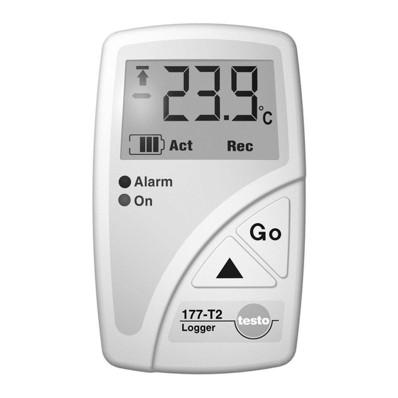
177-T2 Readings Top alarm value Units Bottom alarm value Battery capacity Reading and status information * testo 177-T3 testo 177-T4, testo 177-H1 Readings Top alarm value Units Channels Reading and Bottom alarm value status Battery capacity information *... -
Page 10: Led Functions
24 hours ago 9. Changing battery, P. 26) The LED functions can be switched on/off via software. testo ComSoft In all modes: The Alarm led flashes three times every 15 seconds if the Alarm led remaining battery capacity is less than10% (even if Alarm led is (red LED) deactivated). -
Page 11: Display Sequence
The readings from Start ( All readings ) or From time mark can be read out on the fast printer or the testo 575 testo ComSoft software. The readings from Start ( All readings ) can be read out on the data collector. -
Page 12: Mounting
5. Mounting 5.1 Mounting the wall holder Mounting materials (e.g. screws, dowels) are not included. 1 Position the wall holder at the required location. 2 Using a pencil or similar, mark where the fixing screw is to go. 3 Prepare the area for mounting (e.g. drill a hole, put in dowel). 4 Mount the wall holder using a screw which fits. -
Page 13: Connecting Probes/Switch
Ensure that the probe is positioned properly to avoid disturbing influences on the measurement. testo 177-T3 Use the enclosed twin-wire cable to connect the switch (door contact). Connect a potential-free button or switch to it. -
Page 14: Programming
7.1 Installing software In order to program your data logger in accordance with your individual needs, you will need a PC on which the testo ComSoft software is installed. You will find instructions on the installation and operation of the software in the instruction manual. -
Page 15: Setting Up The Connection
2 Select Instrument > New device . - The New device setup wizard opens. 3 Select testo175-177 in Device selection and click on Next . 4 Select the interface in Connection , with which you have connected your data logger to your PC and click on Next . -
Page 16: Opening The Connection
PC when the connection is opened. Carry out the following to transmit the readings: Click twice on the title of the protocol (See testo ComSoft software instruction manual). Use one connection for several data loggers You can connect different data loggers once a connection has been set up. -
Page 17: Programming The Data Logger
Read out any data from the data logger which may exist before programming (See software instruction manual). testo ComSoft Select Instrument > Device control . This function is only activated if the name of the connection is highlighted. If this is not the case: First click on the name of the connection so that it is highlighted and then select Instrument >... - Page 18 7. Programming Instrument You can read general information on the data logger in the Instrument window. This window is a pure information window. Programming is not possible. Protocol You can read information from the protocol currently stored in the data logger in the Protocol window. You can choose to display All values and Since time mark .
- Page 19 7. Programming Probes Probes: Activate the probes available or deactivate them. Unit: Displays the set unit for the respective channel. You cannot change the unit in this window, but in the Settings window. The lower alarm limit for the channels is entered here. The upper alarm limit for the channels is entered here.
- Page 20 Select the required temperature unit for the temperature channels ( °C or °F ). - Function: testo 575 testo 580 Select whether the data logger is to be newly programmed ( New programming ) and stopped ( Stop ) via the...
- Page 21 Only the data display is deactivated when the display is switched off. Status information on mode and battery capacity are always shown. Enable limit signal output From ComSoft Version 3.4 on, the external alarm signal output testo 581 can be activated if connected to a data logger.
- Page 22 The smallest/largest measuring rate differs depending on the instrument type (Refer to 11. Technical data, P. 28). Measuring rate Door ( only): testo 177-T3 Select the time rate in which the measurements are to take place, if the contact is closed electrically. Stop criterion: Select the required criterion to stop the measuring program.
- Page 23 : Date/Time is not possible as Stop criterion if testo 177-T3 door contact is activated. Duration: Indicates running time of program calculated on the basis of the values for Start criterion , Measuring rate and Stop criterion .
-
Page 24: Closing The Connection
7. Programming Start and Stop: Click on Start to start a measuring program.. This function can only be selected if PC start has been selected as Start criterion . Click on Stop to end a measuring program. This function can only be selected if a measurement is running. -
Page 25: Reading Out Data
ComSoft 3 Professional (0554.0830) like , but with the following additional testo ComSoft 3 Basic features: - Programming and reading out other Testo instruments such , etc. testo 400 testo 650 - Display and printout as number box, histogram, form, analog... -
Page 26: Changing The Battery
6 Connect the new battery to the data logger`s plug-in connection and place in battery compartment. Only original Testo spare batteries should be used (see 12. Accessories/Spare parts, P. 34 for Part nos). 7 Remove the jumper from the plug connector. -
Page 27: Error Messages
10. Error messages If problems occur which are not described here, please contact Testo or your local distributor. You will find contact details in the Warranty booklet or in Internet at www.testo.com . Error message Possible causes Remedy / Comments... -
Page 28: Technical Data
11. Technical data 11.1 testo 177-T1 Parameter ............Temperature (°C/°F) Sensor ..................NTC Number of measuring channels ........1 x internal Measuring range ............-40 to +70 °C Accuracy ..........±0.4 °C (-25 °C to +70 °C) ............±0.8 °C (-40 °C to -25,1 °C) ....................±1 digit Resolution ................0.1 °C... -
Page 29: Testo 177-T2
11. Technical data 11.2 testo 177-T2 Parameter ............Temperature (°C/°F) Sensor ..................NTC Number of measuring channels ........1 x internal Measuring range ............-40 to +70 °C Accuracy ..........± 0.4 °C (-25 to +70 °C) ..............± 0.8 °C (-40 to -25,1 °C) ....................±1 digit Resolution ................0.1 °C... -
Page 30: Testo 177-T3
11. Technical data 11.3 testo 177-T3 Parameter ............Temperature (°C/°F) Sensor ..........NTC (internal and external) Number of measuring channels ..4 channel (2x ext./1x int./ ............1x event, e.g. door contact) Measuring range ........-40 to +70 °C (internal) ..............-40 to +120 °C (external) Accuracy, internal ........±0.8 °C (-40 to -25,1 °C) -
Page 31: Testo 177-T4
11. Technical data 11.4 testo 177-T4 Parameter ............Temperature (°C/°F) Sensor ..........Type K, T and J thermocouples Number of measuring channels ........4 x external Measuring range Type K........-200 to +1000 °C Measuring range Type T ........-200 to +400 °C Measuring range Type J ........-100 to +750 °C Accuracy Logger ........±0.3 °C (-100 to +70 °C) -
Page 32: Testo 177-H1
11. Technical data 11.5 testo 177-H1 Parameter ......Humidity (%RH) / Temperature (°C/°F) / ..............Dew point (td°C/td°F) Sensor ........Humidity sensor / NTC (internal) / ................NTC (external) Number of measuring channels ..4 (3 x internal: %RH, °C/°F, ............td°C/td°F, 1 x external: °C/°F) Measuring range ............0 to 100%RH... -
Page 33: Battery Life
11. Technical data 11.6 Battery life Typical approximate values for the expected battery life are included in the programming windows of the software. These values are calculated on the basis of the following factors: - Measuring rate - Number of probes connected - Status led (green LED) activated/deactivated The calculated data is only an approximation since the battery life depends on many additional factors. -
Page 34: Accessories/Spare Parts
10 years Self-adhesive label thermal paper for printer (6 rolls) 0554 0561 Software Set for incl. interface, desk-top holder and 0554 1774 testo ComSoft 3 Basic testo 175 PC connection cable Software (without interface) 0554 0830 testo ComSoft 3 Professional Interface for incl. - Page 35 12. Accessories/Spare parts Accurate NTC probes for testo 177-T3 testo 177-H1 data loggers Description Illustration Meas. range Part no. -20... +70 °C 0628 7510 35 mm Stub probe * Ø 3 mm -20... +90 °C 0628 7503 40 mm Mounting probe with aluminium sleeve, IP65 Cable length: 2.40 m *...
- Page 36 12. Accessories/Spare parts Accurate thermocouple probes for data loggers testo 177-T4 Description Illustration Meas. range Part no. Mounting probe with stainless steel sleeve -100... +205 °C 0628 7533 40 mm and mini T/C plug, IP 54 Cable length: 1.90 m Ø...
- Page 37 notes...
- Page 38 notes...
- Page 39 notes...
- Page 40 AG Postfach 11 40, 79849 Lenzkirch Testo-Straße 1, 79853 Lenzkirch Telefon: (07653) 681-0 Fax: (07653) 681-100 E-Mail: info@testo.de Internet: http://www.testo.com 0971.1770/04/T/dr/06.02.2007...
Need help?
Do you have a question about the 177 and is the answer not in the manual?
Questions and answers