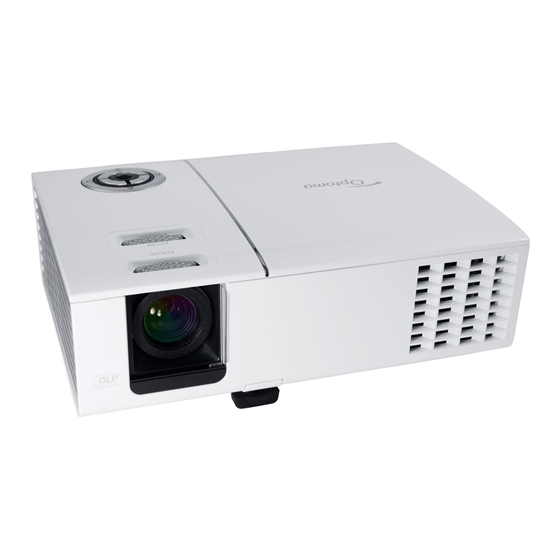
Advertisement

SERVICE MANUAL

Date
Revise Version
2008/2/3
Copyright February.2008. All Rights Reserved P/N: 36.8AE03G001
95.8AE01G00A ; 95.8AE01G019 ; 95.8AE01G001; 95.8AE01GC0A ; 95.8AE01GC0B ;
95.8AE01GC0C ; 95.8AE01GC0H ;95.8AE01GC0J ; 95.8AE01GC0L; 95.8AE01GC0T ;
95.8AE01GC1A ; 95.8AE02G019 ; 95.8AE02GC0E ; 95.8AE02GC0K
SI :
Corrine
HD71/HD710/HD75
V1.0
TSE:
Description
Initial Issue
Check:
Approved:

Advertisement

Table of Contents
loading

Summary of Contents for Optoma HD710

  • Page 1: Service Manual

    SERVICE MANUAL HD71/HD710/HD75 Date Revise Version Description 2008/2/3 V1.0 Initial Issue Copyright February.2008. All Rights Reserved P/N: 36.8AE03G001 95.8AE01G00A ; 95.8AE01G019 ; 95.8AE01G001; 95.8AE01GC0A ; 95.8AE01GC0B ; 95.8AE01GC0C ; 95.8AE01GC0H ;95.8AE01GC0J ; 95.8AE01GC0L; 95.8AE01GC0T ; 95.8AE01GC1A ; 95.8AE02G019 ; 95.8AE02GC0E ; 95.8AE02GC0K...
  • Page 2 70.87U06G001 LAMP DRIVER OSRAM RGBRYB 2X ,3x_ OSRAM 6S W42 39.8AE03G002 PAL WAVEFO 39.87J03G001 WAVEFORM 70.8AE13G001 ASSY MB PCBA HD710 70.8AE02G001 ASSY MB PCBA HD71 PCBA MAIN BD1 ENTEK PCBA MAIN BD1 ENTEK 80.8AE01G011 FOR HD710 80.8AE01G002 FOR HD71 HD71/HD710/HD75 Confidential...
  • Page 3 Preface This manual is applied to HD71/HD710/HD75 projection system. The manual gives you a brief description of basic technical information to help in service and maintain the product. Your customers will appreciate the quick response time when you immediately identify problems that occur with our products.
  • Page 4: Table Of Contents

    Disassemble Thermal Switch,Blow Duct Rubber 2-11 Disassemble Color Wheel and Photo Sensor Board 2-12 Disassemble DMD Chip and DMD Board 2-13 Disassemble Zoom Ring 2-14 Disassemble Focus Ring 2-15 Disassemble ROD Module 2-16 Disassemble Blower Module 2-17 Disassemble Limit Switch 2-18 HD71/HD710/HD75 Confidential...
  • Page 5 Test Inspection Procedure PC Mode Video Performance Optical Performance Measure 4-10 Others 4-11 Chapter 5 Firmware Upgrade Equipment Needed DLP Composer Lite Setup Procedure USB Driver Upgrade Procedure Firmware Upgrade Procedure Chapter 6 EDID Upgrade EDID Introduction Equipment Needed HD71/HD710/HD75 Confidential...
  • Page 6 Setup Procedure EDID Key-In Procedure Appendix A Exploded Overview Appendix B Serial Number System Definition PCBA Code Definition HD71/HD710/HD75 Confidential...
  • Page 7: Chapter 1 Introduction

    - 6.5lbs Max Power Supply - Input 100-240V, 50-60 Hz Resolution - Native resolution 1280x720 - 2000 lumens (typical) ( HD71/HD710) - 1750 lumens (minimum) (HD71/HD710) Brightness - 1100 lumens (typical) (HD75) - 990 lumens (minimum) (HD75) - 1800:1 full on/off (typical)
  • Page 8 (For quick FW upgrade) - RS232 (3pin) - 12 Volt Trigger - Audio Input 3.5mm stereo jack socket x3 (1 audio in for composite & svideo,1 audio in for VGA & DVI and 1 audio in for component) Confidential HD71/HD710/HD75...
  • Page 9: Compatible Mode

    1-2 Compatible Mode Analog Compatibility Resolution V-Sync [Hz] 640x480 848x480 720x400 800x600 SVGA 800x600 1024x768 1024x768 1024x768 1280x768 WXGA 1280x768 1280x768 1280x720 1280x720 1920x1080 1920x1080 1280x1024 SXGA 1280x1024 1280x1024 SXGA+ 1400x1050 1152x870 75.06 MAC G4 640x480 i Mac DV 1024x768 Confidential HD71/HD710/HD75...
  • Page 10 Digital Compatibility Resolution V-Sync [Hz] 800x600 800x600 SVGA 800x600 848x480 1024x768 1024x768 1024x768 1024x768 1280x720 1280x720 1280x720 Wide 1920x1080 1920x1080 1920x1080 Confidential HD71/HD710/HD75...
  • Page 11: Disassembly Process

    * Before you start: This process is protective level II. Operators should wear electrostatic chains. * Note: 1. If you need to replace the main board, you have to get into service mode and record the lamp usage hour. 2. Take HD71 as an example, HD710/HD75 is the same with HD71 HD71/HD710/HD75 Confidential...
  • Page 12: Disassemble Top Cover

    1. At “OPEN” mark,pull the Top Cover to left side ( as yellow arrow) 2. Unscrew 5 screws (as red circle) 3. Disassemble 1 FPC cable to disassemble Top Cover (as green square) Note: There are 8 tenons (as yellow circle) HD71/HD710/HD75 Confidential...
  • Page 13: Disassemble Keypad Board,Keypad And Fpc Cable

    Board,Keypad and FPC cable 1. Unscrew 2 screws (as red circle) 2. Unplug 1 connector to disassemble FPC cable (as red square) 3.Separate all parts of the Keypad and Key pad Board Note: There are 2 tenons (as yellow square) HD71/HD710/HD75 Confidential...
  • Page 14: Disassemble Lamp Module

    2-4 Disassemble Lamp Module 1. Unscrew 2 screws (as red circle) 2. Disassemble Lamp Module 2-5 Disassemble I/O Cover 1. Unscrew 4 hex screws (as red circle) 2. Disassemble I/O cover HD71/HD710/HD75 Confidential...
  • Page 15: Disassemble Top Shielding

    2-6 Disassemble Top Shielding 1. Unscrew 3 screws (as red circle) 2. Disassemble Top Shielding HD71/HD710/HD75 Confidential...
  • Page 16: Disassemble Main Board

    5. Unscrew 2 screws (as yellow circle) 6. Unplug 1 connector (as green square) 7. Disassemble Audio Board Module 8. Unscrew 2 screws (as blue circle) 9. Unplug 1 connector (as red square) 10. Disassemble Component Board Module HD71/HD710/HD75 Confidential...
  • Page 17: Disassemble Left Cover And Right Cover

    2-8 Disassemble Left Cover and Right Cover 1. Release 3 tenons on the left side (as yellow square) 2. Disassemble Left Cover 3. Release 3 tenons on the right side (as red square) 4. Disassemble Right Cover HD71/HD710/HD75 Confidential...
  • Page 18: Disassemble Fan Module

    2-9 Disassemble Fan Module 1. Unscrew 3 screws (as red circle) 2. Disassemble Fan Module 3. Unscrew 4 screws (as yellow circle) 4. Disassembel Fan and Bracket HD71/HD710/HD75 Confidential...
  • Page 19: Disassemble Lvps Module

    2-10 Disassemble LVPS Module 1. Unscrew 1 ground screw (as yellow circle) 2. Unscrew 4 screws (as green circle) 3. Disassemble Bracket and Mylar 4. Unplug 3 connectors (as yellow square) 5. Disassemble LVPS Module HD71/HD710/HD75 Confidential...
  • Page 20: Disassemble Engine Module

    2-11 Disassemble Engine Module 1. Unscrew 1 screw (as yellow circle) 2. Disassemble Inner Mask 3. Unscrew 4 screws (as red circle) 4. Disassemble Engine Module HD71/HD710/HD75 Confidential 2-10...
  • Page 21: Disassemble Thermal Switch,Blow Duct Rubber

    2-12 Disassemble Thermal Switch,Blow Duct Rubber 1. Unscrew 1 screw to disassemble Thermal Switch (as red circle) 2. Disassemble Blow Duct Rubber HD71/HD710/HD75 Confidential 2-11...
  • Page 22: Disassemble Color Wheel And Photo Sensor Board

    2-13 Disassemble Color Wheel and Photo Sensor Board 1. Unscrew 2 screws (as red circle) 2. Disassemble Color Wheel Module 3. Unscrew 1 screw (as yellow circle) 4. Disassemble Color Wheel and Photo Sensor Board HD71/HD710/HD75 Confidential 2-12...
  • Page 23: Disassemble Dmd Chip And Dmd Board

    2-14 Disassemble DMD Chip and DMD Board 1. Unscrew 4 Hex screws (as red circle) to disassemble Heat Sink, DMD Chip and DMD Board. Note: - Remove thermal pad carefully and stick a new one if the thermal pad broken HD71/HD710/HD75 Confidential 2-13...
  • Page 24: Disassemble Zoom Ring

    2-15 Disassemble Zoom Ring 1. Unscrew 1 screw (as red circle) 2. Disassemble Zoom Ring HD71/HD710/HD75 Confidential 2-14...
  • Page 25: Disassemble Focus Ring

    2-16 Disassemble Focus Ring 1. Unscrew 3 screws around Focus Ring (as red circle) 2.Disassemble Focus Ring HD71/HD710/HD75 Confidential 2-15...
  • Page 26: Disassemble Rod Module

    2-17 Disassemble ROD Module 1. Unscrew 2 screws (as red circle) 2. Take off Mylar 3. Unscrew 3 screws (as yellow circle) 4. Disassemble ROD Module HD71/HD710/HD75 Confidential 2-16...
  • Page 27: Disassemble Blower Module

    2-18 Disassemble Blower Module 1. Unscrew 3 screws (as red circle) 2. Disassemble Blower Module and separate Blower and Rubber HD71/HD710/HD75 Confidential 2-17...
  • Page 28: Disassemble Limit Switch

    2-19 Disassemble Limit Switch 1. Unscrew 1 screw (as red circle) 2. Disassemble Limit Switch HD71/HD710/HD75 Confidential 2-18...
  • Page 29: Disassemble Engine Mask Plat And Lamp Driver

    2-20 Disassemble Engine Mask Plate and Lamp Driver 1. Unscrew 2 screws (as red circle) 2. Disassemble Engine Mask Plate and Lamp Driver HD71/HD710/HD75 Confidential 2-19...
  • Page 30: Disassemble System Support Shielding Module

    2-21 Disassemble System Support Shielding Module 1. Unscrew 2 screws (as red circle) 2. Disassemble System Support Shielding Module HD71/HD710/HD75 Confidential 2-20...
  • Page 31: Disassemble Speaker

    2-22 Disassemble Speaker 1. Unscrew 2 screws (as red circle) 2. Disassemble Speaker HD71/HD710/HD75 Confidential 2-21...
  • Page 32: Disassemble Lens Case,Lens Door,Lens Door Switch

    2-23 Disassemble Lens Case,Lens Door, Lens Door Switch 1. Unscrew 2 screws (as red circle) 2. Disassemble Lens Case,Lens Door,Lens Door Switch HD71/HD710/HD75 Confidential 2-22...
  • Page 33: Disassemble Ir Board,Ir Lens

    2-24 Disassemble IR Board,IR Lens 1. Release 2 tenons (as red circle) 2. Disassemble IR Board,IR Lens HD71/HD710/HD75 Confidential 2-23...
  • Page 34: Rod Adjustment

    Note: - To avoid over adjust the rod. - “Screw 1” should be adjusted first, and then adjust the “Screw2”. After the opration,please use the glue to fixed the screws. HD71/HD710/HD75 Confidential 2-24...
  • Page 35 - Press (Power→Source→Source→Up) to get into service mode 2. Use "Up" or "Down" button move the light mark to "Exit" then Use left or right key to re-write the lamp hour back to previous lamp usage hour 3. Choose exit. HD71/HD710/HD75 Confidential 2-25...
  • Page 36: Chapter 3 Troubleshooting

    Lemp-LED Message (Red) (Red) (Green/Red) Standby State Amber (input power cord) Power on Flashing (Warming) Green Lamp Lighting Green Error (Over Temp) Error Flashing (Fan Fail) (1 sec on,1 sec off) Error (Lamp Fail) Note:Steady Light: No Light: HD71/HD710/HD75 Confidential...
  • Page 37: Main Procedure

    - Do “Reset(All data)” of the OSD Menu - Ensure that the signal cables and source are work as well - Check Lamp Module Image Flicker - Check Color Wheel - Check DMD Board - Check Main Board HD71/HD710/HD75 Confidential...
  • Page 38 - Check Main Board - Check DMD Board - Check DMD Chip - Do “Reset(All data)” of the OSD Menu - Adjust Color Wheel Index Color Abnormal - Check Main Board - Check DMD Board - Check Color Wheel HD71/HD710/HD75 Confidential...
  • Page 39 - Ensure that the signal cables and source are work as well - Clean Speaker Module Audio Abnonrmal - Check Audio Board - Check Main Board - Do “Reset(All data)” of the OSD Menu Function Abnormal - Check Main Board - Check DMD Board HD71/HD710/HD75 Confidential...
  • Page 40: Chapter 4 Function Test & Alignment Procedure

    1. After final QC step, we have to erase all saved change again and restore the OSD default setting. The following actions will allow you to erase all end-users' settings and restore the default setting: (1) Please enter OSD menu. (2) To execute "Reset" function. HD71/HD710/HD75 Confidential...
  • Page 41: Test Condition

    4-4 Test Condition - Circumstance brightness: Dark room less than 5.0 lux. - Inspection distance: 1.8m~2.5m functional inspection. - Screen size: 60 inches diagonal. - After repairing each HD71/HD710/HD75, the unit should be run-in (refer to the table below). Symptom Run-in Time...
  • Page 42: Defect Specification Table

    Unstable pixel (dots) Any pattern A+B=0 Adjacent dark pixel Any pattern (dots) A+B=3 Dark blemish (Dirty) Blue 60 pattern (diameter <1/2 inch) A+B=3 Bright blemish (Dirty) Gary 30 pattern (diameter <1/2 inch) Bright dot on frame Black pattern HD71/HD710/HD75 Confidential...
  • Page 43: Test Inspection Procedure

    (2) Select "Tracking" function and use right or left arrow key to adjust the value to minimize video flicker. - Adjust Resync or Frequency/Tracking/H. Position/V. Position to the inner screen. Inspection item Eliminate visual wavy noise by Rsync, Frequency or Master Tracking selection. HD71/HD710/HD75 Confidential...
  • Page 44 - Test Pattern: blue 60 Inspection item - Dark blemish check.(dirty) Criteria - The bright blemish is unacceptable when it ap- Blue 60 pears on blue 60 pattern. - Ref. below table Note: The defect criteria follows TI specification. HD71/HD710/HD75 Confidential...
  • Page 45 - Adjacent dark pixel. Full white Criteria - The number of the dead pixels should be less or equal to 6 pixels. - Adjacent pixel with each other is unacceptable. - Ref. below table Note: The defect criteria follows TI specification. HD71/HD710/HD75 Confidential...
  • Page 46 - RGBW should all appear normal on the screen and sort from R -G-B-W. - Color levels should be sufficient and normal. SMPTE RP-133 (the unidentified color levels on both left and right sides should not over 8 color levels.) HD71/HD710/HD75 Confidential...
  • Page 47: Video Performance

    - Test equipment: DVD player - Test signal: S-Video Inspection item - Video performance test Inspection Distance - 1.8M ~2.5M Criteria - Check any abnoraml color, line distortion or any noise on the screen. - Check the sound from speaker HD71/HD710/HD75 Confidential...
  • Page 48 Inspection item - Audio performance test Inspection Distance - 1.8M ~2.5M Criteria - Check any abnoraml color, line distortion or any noise on the screen. - Check the sound from speaker - Check “Volume“is normal - Check “Mute“is normal HD71/HD710/HD75 Confidential...
  • Page 49: Optical Performance Measure

    ☼ Brightness Formula Avg. (P1~P9)*1.1m Full white pattern Criteria - 960 lumen (HD71/HD710) - 550 lumen (HD75) 3. Ful On/Full Off Contrast Procedure - Full white pattern & full black pattern - Use CL100 to measure brightness values of full...
  • Page 50: Others

    Factory Default - The factory settings (with appropriate centering, size, geometry distortion, etc.) shall be displayed upon “Recall” is selected from OSD HD71/HD710/HD75 Confidential 4-11...
  • Page 51 It should be locked in the correct place. All plastic parts can not be brocken and dam- Plastic parts aged. Safety or warning All safety and warning label should be visible, label including all contents. All interface connector should be complete and Connector workable. HD71/HD710/HD75 Confidential 4-12...
  • Page 52: Firmware Upgrade

    - DLP Composer - Firmware - Library V7.10330 (library file has to put in PC and set right path in 5-4 step 4) Note: The FW upgrade procedure for HD71/HD710/HD75 is the same. Here, we take HD71 as an example. Hardware : - Projector - Power cord:42.50115G001...
  • Page 53: Dlp Composer Lite Setup Procedure

    1. Choose “DLP Composer Lite V7.1 Setup” Program. 2. Click “Next” buttom 3. Read “License Agreement.” - Choose “I accept and agree to be bound by all the terms and conditions of this License Agreement.” - Click "Next" button. 4. Click “Next” button. HD71/HD710/HD75 Confidential...
  • Page 54 5. Click “Next” button. 6. Click “Next” button. 7. The program is executing"Initializing"status 8. Click “Finish.” HD71/HD710/HD75 Confidential...
  • Page 55: Usb Driver Upgrade Procedure

    - Connect the Projector with PC by USB cable. - It will show as the right picture. - Select the item as red circle show. - Click "Next" button. 2. Installation - Cilck “Finish“ and then the USB driver has been set up successfully. HD71/HD710/HD75 Confidential...
  • Page 56: Firmware Upgrade Procedure

    Note: The system fan and the light will not operated. TM” 2. Execute the “DLP Compose file. 3. Click “edit” and “perferences.” 4. Click “Library.” - Click the “browse” button and navigate to the directory where you put the library file in. HD71/HD710/HD75 Confidential...
  • Page 57 - No projectors found” appears, please unplug the USB Cable and replug, then check Driver. Finally,repeat procedure 7. Click “Reset Bus” to erase the flash memory. 8. If the firmware is ready, click “start download” to process the firmware upgrade. - Click “Yes” to erase the flash memory. HD71/HD710/HD75 Confidential...
  • Page 58 - Unplug USB cable and power cord and replug in power cable. 11. Restart the unit and enter the Service mode to check the firmware version. (To enter Service mode, please refer to Chapter 4 Function Test and Alignment Procedure.) HD71/HD710/HD75 Confidential...
  • Page 59: Edid Upgrade

    Note: If a display device has digital input ports, like DVI or HDMI, but without EDID in its main board, the display device will show no image while the input source is digital signal. HD71/HD710/HD75 Confidential...
  • Page 60 - PC - VGA cable:42.87305G001 - DVI cable:42.83N06G001 - Power adapter for fixture :47.57702G001 - DVI to HDMI adapter for HDMI :42.82B13G001 Note: The EDID upgrade procedure for HD71/HD710/HD75 are the same.Here, we take HD71 as an example. HD71/HD710/HD75 Confidential...
  • Page 61: Setup Procedure

    - In the port selection bar, please choose the port that you use. Example: if you use "COM2" ,choose COM2 in the port selection. - Click on "Model". - Choose the EDID that responses to the model that you choose. HD71/HD710/HD75 Confidential...
  • Page 62 - Message box appears on the screen, then click "OK." 5. Change the cable to Digital - Message box appears on the screen, then click "OK". 6. When the EDID program is completed, a message "OK" will appear on the screen. HD71/HD710/HD75 Confidential...
  • Page 63 “Digital” and“Trans” in the Read item,then click the "Read" button. 10. EDID informations will show the result. 11. Unplug DVI cable from Project then use DVI- HDMI adapter to connector DVI cable and Project. Plug into Project HDMI Port HD71/HD710/HD75 Confidential...
  • Page 64 14. When the EDID program is completed, a message "OK" will appear on the screen. 15. Read EDID “Digital” information - In the Read item,select “Digital”and “Trans”, then click the “Read” button. 16. EDID Informations will show the result HD71/HD710/HD75 Confidential...
  • Page 65 Appendix A D.C. HD71/HD710/HD75 HD71/HD710/HD75 Confidential...
  • Page 66 TAPE 3M J350 17*60mm 51.87K31G001 MYLAR BETWEEN LVPS AND ENGINE 61.00079G001 GROUNDING CABLE CLAMP FN-008 61.87340G001 STAND OFF M3*4L D8.0 2100MP 61.87H02G002 LVPS BRACKET AL 230W P5260 61.87K01G001 TOP SHIELDING EP752 41.82V14G001 EMI GASKET W2*H0.5*L35 MM 41.87M03G001 EMI GASKET W3*H1*L38.6mm HD71/HD710/HD75 Confidential...
  • Page 67 SUN GB1205PKV4-AY 50*20mm BLOW 85.005AGG408 SCREW HEX I/O #4-40 H4*L8 NI Nylok 85.1C224G051 SCREW PAN MECH M4*5 COLOR W/TO 85.1F123G080 Screw Pan Spg+Flt M3x8 Ni 85.WA123G060 Screw Pan Tap M3x5 51.82G29G001 WIRE MOUNTS FW-4D-MKW EP719 61.8AE01G001 MB GROUND BRACKET HD71 HD71/HD710/HD75 Confidential...
  • Page 68 Assy Tpye A Engine Module HD71/HD710/HD75 HD71/HD710/HD75 Confidential...
  • Page 69 ZOOM RING ORBIT EP752 70.86V40G001 ASSY ENGINE MODULE 720P 200W A19 70.8AE14GR01 ASSY ENGINE MODULE HD71 (SERV- ICE) 85.1A323G040 SCREW PAN MECH M3*4 BLACK 51.87J10G001 TEFLON FOR ZOOM RING EP752 51.87J12G001 87J-MIRROR-3M-TAPE 51.87J15G001 TEFLON FOR ZOOM RING BACK EP752 HD71/HD710/HD75 Confidential...
  • Page 70 Assy MB PCBA HD71/HD710/HD75 HD71/HD710/HD75 Confidential...
  • Page 71 HD71/HD710/HD75 Confidential...
  • Page 72 SPONGE BETWEEN CNNT AND MYLAR EP752 52.87J07G001 SPONGE FOR AUDIO BOARD EP752 80.8AE07G001 PCBA AUDIO BD ENTEK FOR HD71 80.8AE06G001 PCBA COMPONENT BD ENTEK FOR HD71 52.8AE02G001 SPONGE FOR COMPONENT BD HD71 52.8AE03G001 SPONGE-2 FOR COMPONENT BD HD71 HD71/HD710/HD75 Confidential VIII...
  • Page 73 Assy Top Cover HD71/HD710/HD75 HD71/HD710/HD75 Confidential...
  • Page 74 KEY BUTTON INNER HD71 51.87K04G001 IR LENS TOP HD71 51.87K22G021 LAMP COVER HD71 75.8AE02G001 BUY ASSY TOP COVER HD71 80.8AE03G001 PCBA KEYPAD BD ENTEK FOR HD71 85.1F123G080 SCREW PAN MECH W/SF M3*8 NI GREEN 35.87J01G001 LAMP WARNING LABEL EP752 HD71/HD710/HD75 Confidential...
  • Page 75 Assy Bottom Cover HD71/HD710/HD75 HD71/HD710/HD75 Confidential...
  • Page 76 51.87K13G001 LENS CASE WXGA EP752 51.87K14G001 LENS DOOR EP752 51.87K15G001 IR LENS FRONT EP752 51.87K17G001 LENS DOOR SWITCH HOLDER EP752 75.8AE03G001 BUY ASSY BOTTOM COVER HD71 80.87M05G001 PCBA IR SENSOR BD FOR EP761 85.WA123G080 Screw Pan Tap M3x8 HD71/HD710/HD75 Confidential...
  • Page 77 Assy IO Cover HD71/HD710/HD75 Item Description Parts Supply 70.8AE24GR01 ASSY IO COVER MODULE HD71 (SERVICE) 51.87K19G021 IO COVER HD71 51.8AE03G001 OVERLAY PC HD71 HD71/HD710/HD75 Confidential XIII...
  • Page 78 SPEAKER 8ohm 2W Fai16 EP752 52.89608G011 SPEAKER SPONGE CR 2t EP752 75.87J06G001 BUY ASSY SYSTEM SUPPORT SHIELDING MODULE EP752 85.1A523G060 SCREW PAN MECH M3*6 NYLOK, GRE 86.0A123G024 HEX NUT M3*0.5P L2.4 Ni 41.82A03G001 BOTTOM COVER EMI GASKET LT20 W HD71/HD710/HD75 Confidential...
  • Page 79 Assy X19 LVPS Module 230W HD71/HD710/HD75 Item Description Parts Supply 42.00451G001 W.A. 16P 2100mm LVPS TO MAIN BD UL1007 EP752 75.87J01G101 ASSY LVPS MATRITEK 200W EP752 HD71/HD710/HD75 Confidential...
  • Page 80 Assy Lamp Drive OSRAM 230W HD71/HD710/HD75 HD71/HD710/HD75 Confidential...
  • Page 81 SPACER SUPPORT SCK-3A 51.87K18G001 LIMIT SWITCH HOLDER EP752 70.8AE14G001 OSRAM O3 MID 200W LAMP DRIVER OSRAM O3 MID 200W LAMP DRIVER 70.8AE23GR01 (SERVICE) 75.87K03G001 ASSY LAMP DRIVER OSRAM BRK EP752 85.1F123G080 SCREW PAN MECH W/SF M3*8 NI GREEN HD71/HD710/HD75 Confidential XVII...
  • Page 82 Assy Fan 8025 Module HD71/HD710/HD75 Item Description Parts Supply 85.1A323G080 Screw Pan M3x8 Black 41.87M02G001 GASKET W3*H1*L80 49.87J01G003 SUNON PSD1208PTV1-A 80*25mm AXIAL 61.87H01G003 FAN 8025 BRACKET P5271 HD71/HD710/HD75 Confidential XVIII...
  • Page 83 Assy Blower 5020 HD71/HD710/HD75 Item Description Parts Supply 49.87J02G002 SUN GB1205PKV4-AY 50*20mm BLOWER 52.87306G001 RUBBER BLOWER FAN FRAME 2100MP HD71/HD710/HD75 Confidential...
  • Page 84 Assy Engine Module 720P 200W A19 HD71/HD710/HD75 HD71/HD710/HD75 Confidential...
  • Page 85 SCREW PAN MECH M3*4 BLACK 85.1A323G080 SCREW PAN MECH M3*8 Ni NYLOK 70.8AE18G001 ASSY COLOR WHEEL MODULE 70.87J03GR01 ASSY COLOR WHEEL MODULE EP752(RMA) 51.86V05G001 ENGINE THERMAL MYLAR X19 61.86V05G003 ENGINE WIND GUIDER AL X19. 80.87M04G001 PCBA PHOTO SENSOR BD FOR EP761 HD71/HD710/HD75 Confidential...
  • Page 86 Assy Engine Top Cover Module WXGA 200W HD71/HD710/ HD75 HD71/HD710/HD75 Confidential XXII...
  • Page 87 51.87W05G001 FOCUS RING BASE LIGHTCUT P5370W 52.86V12G002 DMD BD SUPPORT RUBBER A19 WASHER AL FOIL + ELECTRIC CONDUCT 61.83U10G001 TAPE0.2t TDP-T9 51.86V08G001 DMD ADJUST MYLAR A19 61.86V27G002 ENGINE TOP COVER MG A19 51.86V09G002 TEFLON FOR ZOOM RING X19 TYPE HD71/HD710/HD75 Confidential XXIII...
  • Page 88 D.P HD71/HD710/HD75 PC (Packing Procedure Drawing) HD71/HD710/HD75 Confidential XXIV...
  • Page 89 35.00040G001 LABEL 30mm,GREEN 35.82001G111 LABEL CARTON 3”x3” BLANK PJ885 35.86301G001 SPEC LABEL BLANK PD120 35.52302G091 LABEL CARTON 108*92 BLANK 51.00093G002 PE BAG 400*520*0.07mm FOR OPTOMA 51.00200G001 HANDLE BAR 2. PE HD70 51.00201G001 HANDLE BAR 1.PE HD70 55.8AE01G001 CARTON OUTSIDE AB FLUTE HD71 56.83C03G002 PACKING EPE PAPER #535*450*0.8...
  • Page 90 I. Serial Number System Definition Serial Number Format for Projector WW AAAAA 0001 Q = Optoma BBB = Project code Y = Last number of the manufacture year (ex:2007 = 7) WW = week of the manufacture year ( ex:the thirty-three week of...
  • Page 91 PCBA Code Definition PCBA Code for Projector XXXXXXXXXX EEEE Vendor Code Revision Date Code HD71/HD710/HD75 Confidential...

This manual is also suitable for:

Hd71Hd75

Table of Contents