Table of Contents
Advertisement
Advertisement
Table of Contents

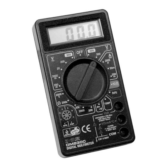
Summary of Contents for ITC IDMM-100
-
Page 2: Warranty
SAFETY ITC multimeters have been designed according to IEC- 1010 concerning electronic measuring instruments with a measurement category (CAT II 600V). The max. permitted transient voltage: 4000V, and pollution2. - Page 3 • Do not use the meter if it is damaged. Before you use the meter, inspect the case. Pay particular attention to the insulation surrounding the connectors. • Inspect the test leads for damaged insulation or exposed metal. Check the test leads for continuity.Replace damaged test leads before you use the meter.
- Page 4 • Never use the meter to measure current if the circuit to be measured might contain voltage exceeding 250V. • Temperature measurement should be performed on non- active part or insulation material only. • Remaining endangerment: When an input terminal is con nected to dangerous live potential it is to be noted that this potential at all other terminals can occur! •...
-
Page 5: Maintenance
MAINTENANCE • Before opening the case, always disconnect the test leads from all live circuits. • For continued protection against fire, replace fuse only with the specified voltage and current ratings: • F 250mA/250V (Fast Blown), ø5 x 20 • Periodically wipe the case with a damp cloth and mild detergent. -
Page 6: Specifications
SPECIFICATIONS Accuracy is specified for a period of one year after calibration and at 23±5ºC with relative humidity up to 75%. Accuracy specifications take the form of: ± [ % of Reading] ± [number of Least Significant Digits] DC VOLTAGE RANGE RESOLUTION ACCURACY... - Page 7 DC CURRENT RANGE RESOLUTION ACCURACY 200 µA 100 mA 2000 µA 1 µA ± 1.0% ± 5D 20 mA 10 µA 200 mA 100 µA ± 1.2% ± 5D 10 A 10 mA ± 2.0% ± 5D Overload protection: F 250 mA / 250 V Fused (10A unfused) RESISTANCE RANGE RESOLUTION...
-
Page 8: Signal Output
DIODE & BUZZER Diode: Testing Voltage about 2.8V, current about 1 mA. The approximate forward voltage drop in mV will be displayed. Buzzer: The buzzer will sound when the resistance is less than about 50Ω. SIGNAL OUTPUT Signal output: 50 Hz, square wave output Level output: 3 Vp-p BATTERY TEST... -
Page 9: General Specifications
GENERAL SPECIFICATIONS Display: 3-1/2 digit LCD with a max. reading of 1999 Polarity: Auto polarity indication Over-range indication: Only figure “1” on the display Operating Environment: temp. 0 - 40ºC; < 75% RH Storage environment: temp. -15ºC - 50ºC; < 85% RH Battery: 9V 6F22 Low Battery Indication:... -
Page 10: Battery And Fuse Replacement
BATTERY & FUSE REPLACEMENT When battery is not sufficient, LCD will display. You will need a 9 V battery. The fuse rarely needs to be replaced and is blown as a result of the operator’s error. To replace the fuse, open the case and replace the blown fuse with the ratings specified: F 250mN250V.
Need help?
Do you have a question about the IDMM-100 and is the answer not in the manual?
Questions and answers