Table of Contents
Advertisement
Quick Links
Download this manual
See also:
Installation Manual
Advertisement
Table of Contents

Related Manuals for BrainQ RSC/2

Summary of Contents for BrainQ RSC/2
- Page 1 USER MANUAL BrainQ RSC/2 Thermostat...
- Page 2 English...
-
Page 3: Table Of Contents
Contents Control level ................Display and operating instruments GB-5 Operation - display - standard display . - Page 4 Page GB-4 Copying of timeprograms (forming of blocks) ................GB-16 Deletion of timeprograms –...
-
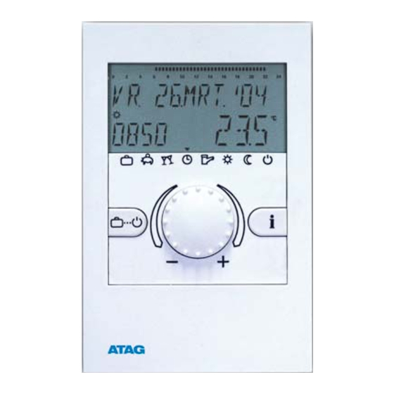
Page 5: Display And Operating Instruments
Display and operating instruments Time bar heating times Date LCD display Actual room temperature Time Program selection key with corresponding Displaying operating information including program symbols temperatures Rotary pushbutton Page GB-5... - Page 6 Page GB-6 Operation Symbolism used in this manual: The centrally arranged rotary pushbutton and the keys labeled with symbols facilitate ease of operati- on. It is, however, recommended to read this manual attentively to be informed about the repeating steps. –...
-
Page 7: Temporary Change Of Room Temperature
Temporary change of room temperature By short-term pressing of the rotary pushbutton in the standard display the required room tempera- ture can be corrected as shown in the opposite schematic. current temperature setting A room temperature correction can be made in the Temperature operating modes AUTOMATIC, ABSENT and R R O O O O M M T T E E M M P P... -
Page 8: Operational Mode Selection For Heating And Hot Water (Synoptic
Page GB-8 Operational mode selection for heating and hot water With this button the required operational mode for heating and hot water circuit is selected. It appears in the text on the display, simultanously an arrow at the lower edge of the display points to the appertaining program symbol. Select: When pressing the operational mode selector button, the currently active mode is indicated by flashing. - Page 9 Function of operational modes (with common adjustment, see page 24) Automatic Heating Red. heating Standby Summer DHW Holiday til ... Absent til ... Party til ... (according to (HC=permanent (HC=permanent night HC=off, frost protection (HC=off, DHW=off) (temporary set back) (temporary heating) (HC=off, DHW=off)* temp.) time program)
-
Page 10: Plant Information
Plant information Page GB-10 ¤ ¤ Entry into the plant information Information button for the enquiry of the hea- ¤ ting system, temperatures etc. The query is O O U U T T S S I I D D E E made by turning the rotary pushbutton and 1 1 3 3 . -
Page 11: Info-Time
indicates of heating circuit pump and boiler pump Room temperature Domestic hot water tank R R O O O O M M T T E E M M P P H H C C D D H H W W temperature Unmixed heating circuit –... - Page 12 Page GB-12 Programming level – level synoptic 10 12 14 16 Standard display W W E E . . 2 2 5 5 . . J J U U N N . . 0 0 3 3 °C 2 2 0 0 . . 5 5 (e.g.
- Page 13 Parameter 03 Parameter 27 Parameter 16 HEATINGSTART Separate operation DAY-MONTH Domestic hot water Heating curve common (1) selected cycle temperature adjustment (slope) separate back forward back forward back forward back forward Parameter 04 TIMECHANGE HEATINGEND Summer ECO- SUMMER - WIN- temperature selected cycle (Heating limit)
-
Page 14: Programming Of Timeprograms
Page GB-14 Programming of operating times With this mode of operation individual timeprograms can be generated for heating and hot-water W W E E 2 2 5 5 . . J J U U N N . . ; ; 0 0 3 3 Standard display mode. - Page 15 10 12 14 16 10 12 18 20 10 12 14 16 10 12 14 16 10 12 14 16 0 0 6 6 . . 0 0 0 0 - - 2 2 2 2 . . 0 0 0 0 - - - - .
-
Page 16: Copying Of Timeprograms (Forming Of Blocks
Page GB-16 Copying of timeprograms (formation of blocks) W W E E 2 2 5 5 . . J J U U N N . . ; ; 0 0 3 3 Standard display 2 2 0 0 . . 5 5 °C 1 1 5 5 : : 3 3 0 0 With this function the timeprograms of any weekday can be copied to other days... - Page 17 accept C C O O P P Y Y Source select Setting range: Monday (MO)...Sunday (SU) Change - Exit : M M O O F F R R O O M M Example: Each flashing adjustment value can be cor- Monday rected by means of the rotary pushbutton accept...
- Page 18 Page GB-18 Reloading of standard program - deleting of individual timeprogram W W E E . . 2 2 5 5 . . J J U U N N . . ; ; 0 0 3 3 Standard display 2 2 0 0 . . 5 5 °C 1 1 5 5 : : 3 3 0 0 An individually generated timeprogram can be replaced by its stan-...
- Page 19 if necessary select program, if enabled (see page 23) Reset 3 sec press approx. 3 seconds Standard program was reloaded R R E E S S E E T T Individual program was deleted! O O K K Standard timeprograms Timeprogram P1 Timeprogram P2 (see page 22) Circuit...
-
Page 20: Table For Individual Timeprograms
Page GB-20 Table for individual timeprograms Timeprogram P1 Timeprogram P2 Timeprogram P3 Cycle 1 Cycle 2 Cycle 3 Cycle 1 Cycle 2 Cycle 3 Cycle 1 Cycle 2 Cycle 3 from from from from from from from from from Cycle 1 Cycle 2 Cycle 3 Cycle 1... - Page 21 TIME-DATE Entry: see level synoptic page 12-13 T T I I M M E E - - D D A A T T E E ¢ ¢ Exit: Button or automatically after approx. Entry: 60 seconds. Change: Accept selected flashing value by pressing the rotary pushbutton.
-
Page 22: Extended Installer Level
Page GB-22 EXTENDED INSTALLER LEVEL The extended installer level contains the levels SYSTEM, DHW Code input and UNMIXED CIRC. After the input of the corresponding code the parameters accessible for the heating specialist will be relea- sed and are then accessible for editing, in dependence on the ¢... - Page 23 SYSTEM Entry: Note: Only accessible with code 1234. see level synoptic page 12-13 S S Y Y S S T T E E M M Exit: ¢ ¢ Contents: General limitation parameters and functions, which Button or automatically after approx. S S Y Y S S T T refer to the respective heating system.
- Page 24 Page GB-24 Parameter 3 - Separate operation P P A A R R A A M M E E T T E E R R 0 0 3 3 Setting range: 1 = common selection 2 = separate selection S S Y Y S S T T Factory setting: 1 Common selection: Application: Objects with identical use of characteristics...
- Page 25 Parameter 4 - Summer ECO-temperature* P P A A R R A A M M E E T T E E R R 0 0 4 4 Setting range: OFF, 10.0 to 30.0 °C S S Y Y S S T T 2 2 0 0 .
-
Page 26: Parameter Reset
Page GB-26 Parameter reset R R E E S S E E T T With this function all changes made in the programming levels S S Y Y S S T T can be reset to the factory setting. Exceptions: Time-date, operating times Reset: With the readiness for reset (SET) flashing press the Important: A reset should only be made if all individually P P A A R R A A M M . - Page 27 Entry: see level synoptic page 12-13 Note: Only accessible with code 1234. D D H H W W Exit: Button ¢ ¢ or automatically after approx. This level includes the necessary parameters to adjust the dome- D D H H W W 60 seconds.
- Page 28 Page GB-28 Parameter 16 - Hot water temperature P P A A R R A A M M E E T T E E R R 1 1 6 6 Setting range: 10.0 °C to DHW maximum limit 6 6 3 3 . . 0 0 °C D D H H W W Factory setting: 63 °C...
- Page 29 DIRECT HEATING CIRCUIT Entry: see level synoptic page 12-13 Note: Only accessible with code 1234. U U N N M M I I X X E E D D C C I I R R C C . . Exit: ¢...
- Page 30 Page GB-30 Parameter 3 - Room sensor display P P A A R R A A M M E E T T E E R R 0 0 3 3 Setting range: OFF*, 1, 3* Factory setting: 1 H H C C This parameter activates the room sensor and enables all para- Note: The room sensor must not be activated:...
- Page 31 Example: Parameter 4 - Room sensor function P P A A R R A A M M E E T T E E R R 0 0 4 4 adjusted room setvalue = 21 °C Setting range: OFF, 1. . . 500 %, RC actual room temperature = 20 °C R R C C Factory setting: RC...
- Page 32 Parameter 5 - Heating curve adaptation Page GB-32 P P A A R R A A M M E E T T E E R R 0 0 5 5 Setting range: ON, OFF adaptation made under following O O N N Factory setting: H H C C conditions:...
-
Page 33: Day Temperature
Parameter 6 - Inrush optimization P P A A R R A A M M E E T T E E R R 0 0 6 6 Setting range: OFF, 1. . . 8 h Factory setting: H H C C This parameter calculates the latest heat-up time within a pre- Application (for weather dependent systems only): determined adjustment value and under consideration of the... - Page 34 Page GB-34 Parameter 26 - Night temperatur (standard value) P P A A R R A A M M E E T T E E R R 2 2 6 6 Setting range: 5.0. . . 30.0 °C 1 1 6 6 . . 0 0 °C Factory setting: 16.0 °C...
-
Page 35: Error Message
Error message Example for sensor error message The control unit contains comprehensive error identification logics, F F L L O O W W (Short-circuit or interruption) which shows both control errors as well as system errors with prio- 1 1 2 2 - - 0 0 rity by means of an associated error code. - Page 36 Notes Page GB-36...
-
Page 37: Technical Specifications
Technical specifications (thermostat) Electrical connection (thermostat) Supply voltage: Via data bus (Protective extra low voltage acc. to EN 60730) Socket (unit removed) Power consumption: 300 mW Bus interface: RS 485 Ambient temperature: 0..0,50 °C Storage temperature: -25..0.60 °C Protection type acc. to EN 60529: IP 20 Protection type acc. - Page 38 ATAG Verwarming Nederland BV Postbus105 7130 AC Lichtenvoorde T: 0544 - 391777 F: 0544 - 391703 info@atagverwarming.com www.atagverwarming.nl Strebel Ltd. 1F, Albany park industrial estate Frimley road, Camberley Surrey GU16 7BP Telephone: (01276) 685422 Fax: (01276) 685405 info@strebel.co.uk www.strebel.co.uk Met deze vernieuwde uitgave vervallen alle voorgaande installatievoorschriften. This renewed publication cancels all previous installation instructions.
Need help?
Do you have a question about the RSC/2 and is the answer not in the manual?
Questions and answers