
Related Manuals for Gehl RS5-19


Summary of Contents for Gehl RS5-19
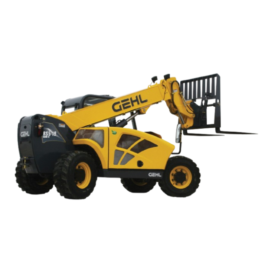
- Page 1 ® Form No. 50960066 Revision A August 2013 RS5-19 Telescopic Handler Beginning with Serial Number 50951...
- Page 2 Indicator and Control Symbols Fasten Seat Belt Safety Alert Engine Oil Hydraulic Oil Axle Oil Brake Fluid Read Operator’s Symbol Manual Diesel Fuel Grease Battery Engine Electrical Engine Oil Engine Coolant Engine Failure Preheat Pressure Temperature Engine Air Filter Hydraulic Filter Transmission Parking Brake Brake Failure...
-
Page 3: Table Of Contents
Warranty ........Inside Back Cover IDENTIFICATION INFORMATION Write the Gehl Telescopic Handler serial number below. Refer to the model and serial number when inquiring about parts or service from your Gehl dealer. MODEL NO. RS5-19 SERIAL NO. -
Page 4: Introduction
A storage pocket in the back of the seat is provided for storing the Operator’s Manual. After using the manual, please return it to the pocket and keep it with the unit at all times! If this machine is resold, GEHL Company rec- ommends that this manual be given to the new owner. - Page 5 Identification Telescopic Boom Dash Indicators and Controls Tilt Cylinder Slave Cylinder Quick-attach System Seat Operator’s Station Auxilluary Extend Cylinder Hydraulics Inside Boom Lift Cylinder Exhaust Pipe Rear Boom Access Cover Rear View Mirror Fuel Tank Behind Access Cover Air Cleaner Hydraulic Tank under Engine Filler under...
-
Page 6: Specifications
Chapter 2 SPECIFICATIONS Lifting Performance Steering System Axles (front and rear) Front Axle: Dana model 60-211-69 Steer Valve: Fixed-displacement rotary Maximum lift capacity: Displacement/Rev: 7.3 cu. in. (120 cc) Drive/steer, limited-slip differential, 5500 lbs. (2495 kg) System pressure: 2400 psi (165 bar) full-time four-wheel drive Maximum lift height: Steer cylinders: 1 per axle... -
Page 7: Checklists
Chapter 3 CHECKLISTS PRE-DELIVERY I acknowledge that the pre-delivery procedures were per- formed on this unit as outlined above. The following Checklist is an important reminder of inspec- tions that MUST be made before delivering the Telescopic Handler to the customer. Check off each item after the pre- Dealership’s Name scribed action is taken. - Page 8 INTENTIONALLY BLANK (To be removed as Dealer’s file copy) 50960066/AP0813 PRINTED IN U.S.A.
-
Page 9: Checklists
Chapter 3 CHECKLISTS PRE-DELIVERY I acknowledge that the pre-delivery procedures were per- formed on this unit as outlined above. The following Checklist is an important reminder of inspec- tions that MUST be made before delivering the Telescopic Handler to the customer. Check off each item after the pre- Dealership’s Name scribed action is taken. -
Page 10: Safety
Chapter 4 SAFETY The above Safety Alert Symbol means ATTENTION! Gehl Company ALWAYS takes the operator’s safety ALWAYS BE ALERT! YOUR SAFETY IS into consideration when designing its machinery, and INVOLVED! It stresses an attitude of safety aware- guards exposed moving parts for his/her protection. - Page 11 SAFETY Additional Safety Reminders WARNING Ü User/operator safety practices, as established by industry standards, are included in this Operator’s Manual and intended to promote safe operation of U.S. OSHA regulations require employers in the machine. These guidelines do not preclude the general industry and the construction, ship- use of good judgment, care and common sense as yard and cargo-handling industries (excepting...
- Page 12 SAFETY Ü Walk around the machine and warn all personnel Ü DO NOT exceed the machine’s rated operating who may be servicing the machine or who are in capacity for the type of attachment tool being used. the machine path prior to starting. DO NOT start Ü...
-
Page 13: Suspended Loads
SAFETY 5. Operator and crew members have been Suspended Load Safety Reminders trained in the safe use and operation of the The handling of suspended loads by means of a truss equipment, including how to avoid electro- boom, winch, boom mounted lift hook or other similar cution. - Page 14 SAFETY Ü Ü ALWAYS wear safety glasses with side shields Use multiple pickup points on the load when pos- sible. Use taglines to restrain the load from when striking metal against metal. In addition, it is swinging and rotating. also recommended that a softer (chip-resistant) material be used to cushion the blow.
- Page 15 Ü This machine is equipped with a horn and backup Ü To ensure continued safe operation, replace dam- alarm. The user must determine if operating condi- aged or worn-out parts with genuine Gehl service tions require the machine to be equipped with parts before using this equipment.
- Page 16 SAFETY L65927 L65928 L65927 L65942 L66613 072798 L70305 L65927 L65933 50960066/AP0813 PRINTED IN U.S.A.
- Page 17 SAFETY 072798 L65927 L65933 L70305 L65928 L65942 L66613 PRINTED IN U.S.A. 50960066/AP0813...
- Page 18 SAFETY L65926 L70307 L70306 101506 100359 L65928 L65932 L70306 L70307 L65928 L65932 100359 L65926 101506 50960066/AP0813 PRINTED IN U.S.A.
-
Page 19: Indicators And Controls
This Gehl machine is designed and intend- ed to be used ONLY with a Gehl Company WARNING attachment tool, or a Gehl Company approved accessory or referral attachment tool. Gehl... - Page 20 DASH PANEL AREA Load Zone Charts: A set of flip charts show lift height and reach lim- its relative to the load weight being handled with various attachment tools. INSTRUMENT AND SWITCH PANEL Located to the right of the steering wheel, this panel contains the instrument gauges, indicator lamps and function switches.
- Page 21 B - Scroll Button: Pressing this button changes the lamp should be off. During starting and when the igni- function displayed in the multi-function display tion is on but the engine is not running, this lamp will screen. be on. Press and hold the button in for 3 seconds to tog- IMPORTANT: If this lamp comes on during nor- gle the engine coolant tmperature reading between...
- Page 22 If this combination is present, con- “ON” position for a momentary lamp check. tact your authorized Gehl dealer. During normal operation all lamps will never all be •...
- Page 23 Switch Panel B - High/Low Speed: This switch is used to select the travel speed. Press the top of the switch to select low speed, used for load pickup and placement, or when- ever low speed operation is desired. Press the bottom of the switch to select high speed, used for road travel.
- Page 24 F - Turn Signal: This switch is used to indicate the direction of a turn with the tail lights. Press the right arrow for a right turn; press the left arrow for a left turn. Return the switch to the center position after the turn is completed.
-
Page 25: Seat Belt
NOTE: The lever MUST be in N (Neutral) position Suspension Seat (option- al): In addition to the “A” before the starter will engage to start the engine. latch handle for forward and IMPORTANT: Care should be taken when chang- rearward adjustment, this ing direction, because damage to the hydrostatic seat has a knob “B”... -
Page 26: Service And Safety Features
Boom Angle machine following the Mandatory Safety Indicator Shutdown Procedure (page 8). DO NOT SERVICE AND SAFETY FEATURES attempt repairs. Call your Gehl dealer for assistance. The following indicators are for checking fluid levels. Coolant Attachment Tilt/Auxiliary Hydraulics Joystick: To... - Page 27 Brake Fluid Reservoir: Located in the front of the Battery: The battery is located under the engine cover frame on the inside left wall under the cover. toward the front of the engine compartment directly to the rear of the air cleaner. Windshield Washer Fluid Reservoir: Located under the cover on the front of the frame.
- Page 28 Operator Station Fuse and Relay Functions: Refer Engine Compartment Fuses, Relays and Solenoids: to the illustration and following description for the fuse Located inside the engine compartment on the firewall. and relay functions. Turn the quater-turn latch to lift the panel from the fire- wall.
- Page 29 C. 20 AMP Relay: Regen Interlock D. 20 AMP Relay: EGR Valve ATTACHMENT TOOLS Gehl offers a versatile range of attachment tools to meet various lifting and material handling applications. Contact your Gehl dealer for specifications and order- ing information.
-
Page 30: Operation And Adjustments
Chapter 6 OPERATION AND ADJUSTMENTS GENERAL INFORMATION IMPORTANT: DO NOT use forks that have been repaired by welding. CAUTION 2. Attachment Tool Mount: No loose or missing parts; no visible damage. Lock pins/plate in the BEFORE starting the engine and operating the locked position. - Page 31 15. Exhaust System: No loose or missing parts; no STARTING THE ENGINE visible damage; no obstructions to the outlet. The following procedure is recommended for starting 16. Hydraulic Cooler and Radiator: No loose or the engine: missing parts; no visible damage; no evidence of 1.
- Page 32 This service will need to FIRST TIME OPERATION be performed by a authorized Gehl dealer. Make sure the engine is warm and then go through the Automatic (AUTO) Exhaust Filter Cleaning...
- Page 33 The Exhaust Filter Cleaning Indicator will illuminate speed will be controlled by the ECU. The machine when the system is actively performing an exhaust fil- must remain parked during this process. ter cleaning. When the exhaust filter cleaning process NOTE: It is not necessary to perform a has completed its cycle, the cleaning indicator will turn manual/parked exhaust cleaning unless a previ- off.
- Page 34 The Exhaust Filter Indicator CHANGING ATTACHMENT TOOLS will illuminate, indicating the the soot level in the filter is The Telescopic Handler boom nose will accept Gehl slightly high. If conditions Quick-attach System attachment tools. The Quick- are safe, the operator should...
- Page 35 1. Raise the boom slightly and extend it 2 to 3 feet Modifications, alterations to, or use of attach- (600-900 mm) for better visibility. Lower the ment tools not authorized by Gehl (or the man- boom until the attachment tool is approximately ufacturer) in writing can void warranty and 12”...
- Page 36 6. Inspect the work area. Be sure you know where Only handle loads within the capacity limits of the you will make load pickups, lifts and turns. Look machine, and which are stable and safely arranged. over the terrain of the jobsite for holes, obstacles, When attachments are used, extra care should be taken slippery surfaces, and soft or deep mud.
-
Page 37: Traffic Flow Patterns
Avoid turning if possible and use extreme caution on grades, ramps and inclines. Normally travel straight up and down the slope. Traffic Flow Patterns Know and understand the traffic flow patterns of your jobsite. Know all Telescopic Handler hand signals for safety. - Page 38 IMPORTANT: DO NOT lower boom at high Be certain you can control both speed and engine speed when attachment tool is at maxi- direction before moving. Always place the mum rearward tilt, because damage to slave machine in neutral and set the parking brake cylinders may result.
- Page 39 Approach the load squarely and slowly with the Analysis: See “Typical Load Zone Chart” below. machine straight and level. Adjust the space between Projecting up from the 5-foot mark on the horizontal forks, if necessary. Engage the load equally on both axis to intersect a line through the 10-foot mark on the forks until the load touches the carriage backrest.
- Page 40 DO NOT attempt to bring down the boom or make Use multiple lift points and taglines to restrain the repairs. Call your Gehl dealer immediately. load from swinging or rotating. As lift height increases, depth perception decreases.
-
Page 41: Road Travel
Carrying Suspended Load With the assistance of a signal person, continue the feathering technique to lower the load into place. WARNING NEVER place the signal person between the load and the telehandler or other stationary objects. Rigging between the load and attachment should Once the load is stationary on the landing point be as short as possible to reduce boom height. - Page 42 Loading Machine Using Ramps WARNING NOTE: A matched pair of ramps is required. NEVER transport the machine with the boom raised or extended. BE SURE to secure the machine (including boom) to the truck or trail- er bed using chain and binders or steel cables, to prevent any movement while trans- porting.
-
Page 43: Towing The Telescopic Handler
1. Using suitable lift equipment, hook into the lift 2. Loosen the jam nut on a high pressure limiter. eyes. Adjust the length of the slings or chains to lift the telescopic handler level. Release Screw IMPORTANT: As needed, use a spreader bar to prevent the slings or chains from rubbing the Jam Nut sides of the boom. -
Page 44: Theft Deterrents
THEFT DETERRENTS WARNING Gehl has recorded all major component part numbers and serial numbers. Users should take as many of the Before the Telescopic Handler can be returned following actions as possible to discourage theft, to aid to service, the SAHR parking brake must be... -
Page 45: Lubrication
Chapter 7 LUBRICATION GENERAL INFORMATION Hydraulic System Reservoir Use Mobil DTE 15M, or an equivalent that contains anti-rust, anti-foam and anti-oxidation WARNING additives and conforms to ISO VG46. Refer to “Severe Operating Conditions” on this page NEVER lubricate or service this unit when any for additional hydraulic oil specifications. -
Page 46: Hydraulic
To ensure continued proper operation, use Drive shaft, slip joint (front axle) ..1 only genuine Gehl replacement filters. Base end lift cylinder pivot pin ..1 Base end slave cylinder pivot pin . - Page 47 Grease Fittings Locations PRINTED IN U.S.A. 50960066/AP0813...
-
Page 48: Service And Storage
The following areas of internal components service replacement and operating adjustments should only be by (or under the direction of) an authorized Gehl WARNING Telescopic Handler dealer. IMPORTANT: DO NOT service or repair major... - Page 49 Before removing one of these valves, you ARE Some of the operator-related services will require REQUIRED to call your Gehl dealer or Gehl access to components located inside the superstructure, Service Department. Failure to do so may under shields, hoods and covers.
- Page 50 Replace any cracked or damaged parts. hydraulic, battery or fuel systems; all contain Use only genuine Gehl parts for service. highly flammable liquids or explosive gases, which can cause an explosion or fire if ignited. Use care not to damage machined and polished sur- faces.
-
Page 51: Checking Coolant
CHECKING FUEL TANK LEVEL Coolant Expansion Tank After operation each day, the fuel tank should be filled to prevent water from condensing in the tank. To fill, remove the filler cap and add fuel. Engine Oil CHECKING FUEL FILTER/WATER SEP- Dipstick ARATOR Visually check the fuel filter/water separator for water... - Page 52 CHECKING HYDRAULIC OIL LEVEL Inflate as necessary per the chart below: The machine must be on level ground with boom low- 12-16.5 NHS 10 PR: 65 psi (450 kPa) ered and completely retracted. The fluid MUST be cool NOTE: If the tires have been filled with water or when checking the reservoir level, to reduce the possi- calcium chloride for ballast, a calcium chloride tire bility of overfilling the hydraulic system.
-
Page 53: New Machine
CHECKING WHEEL NUT TORQUE The semi-transparent seperator cup contains a red float ring. The float ring will rise to the surface of the water On new machines, or any time a wheel has been to show how much water needs to be drained. removed, re-torque until 450 ft.-lbs. -
Page 54: Replacement Filters
chapter for the proper oil specification. Replace the CHANGING ENGINE OIL AND FILTER check/fill plug. Change the engine oil and filter using the following procedure: Check / Fill Plug 1. With the engine warm, open the cover under the engine to access the drain plug. Remove the crankcase drain plug. - Page 55 6. Remove the old filter element from the filter body Fuel Filter and install the new filter element. 7. Position the float ring in the seperator cup. 8. Install the seperator cup to the filter body by tight- ening the cup to the right. 9.
- Page 56 clean the terminals and clamps with the same alkaline WARNING solution. WARNING The ONLY safe method for jump-starting a disharged battery is for TWO PEOPLE to per- form the following procedure. The second per- Explosive gas is produced while a battery is in son is needed for removing the jumper cables use or being charged.
- Page 57 6. After the machine is started and running smoothly, boom. Shims can be added to achieve the proper clear- have the second person remove the jumper cables ance. Loosen the bolts and insert shims until proper (negative (-) jumper cable first) from the jumper clearance is obtained.
- Page 58 Clean any large debris that may have collected on This spin-on type hydraulic filter element is located the top side of the condenser. under the engine cover behind the radiator. Open the engine cover to access the hydraulic filter. Initial Clean the condenser use a jet of compressed air replacement is after the first 100 hours.
- Page 59 The air filter restriction indicator on the multi-function 5. Use a trouble light inside the new outer element to display is lit whenever the air cleaner is restricted. inspect for bad spots, pinholes and ruptures. IMPORTANT: NEVER use an element that is Mounting damaged.
- Page 60 2. Fill the differential with oil as specified in the the drain/fill plug. Repeat this procedure on the Lubrication chapter. When the oil flows from the other three hubs. check hole, replace the plug. Wait 10 to 15 minutes Plug in fill and and repeat this process until the axle is full.
- Page 61 quality water and supplemental coolant additives WARNING (SCAs) suitable for heavy-duty diesel engines. See the engine manual for additional information. Remove the radiator cap only when the engine 8. Pour the coolant slowly into the radiator until the is cool, or painful burns could result. coolant is at the bottom of the filler neck.
-
Page 62: Storing The Machine
(and any adhering dirt) from filter service is required. This professional exhaust fil- the cylinder rods prior to starting the engine. After ter service must be performed by an authorized Gehl operating, BE SURE to recoat the cylinder rods dealer. -
Page 63: Decals
PRINTED IN U.S.A. 50960066/AP0813... - Page 64 WARNING - PINCH POINT L65927 WARNING - JUMP START L65933 ANTI-FREEZE 056859 COOLANT UNDER PRESSURE 072798 HYDRAULIC OIL 137632 GEHL, 1.50 X 6.37 104408 RS5-19 RH 104900 GEHL, 3.7 X 15.92 184043 GEHL, 2.75 X 11.67 184305 GEHL, 8.00 X 33.95 102025...
- Page 65 DESCRIPTION PART NO. WARNING - PINCH POINT L65927 QUICKATTACH DIAGRAM L65937 DANGER-PERSONNEL INJURY L65928 BRAKE FLUID L63474 Gehl, 8.00 X 33.95” 102025 QUICKATTACH UNLOCKED L66613 DIESEL FUEL 50301416 RS5-19, LH 104899 GEHL, 2.00 X 8.49 104833 GEHL, 2.75 X 11.67 184305 PRINTED IN U.S.A.
- Page 66 DECAL LOCATIONS REF. DESCRIPTION PART NO. WARNING-TILT HAZARD/GENERAL OPERATOR L70306 WARNING - CARRY LOAD LOW L65926 F-N-R SHIFT L68295 MADE IN USA 140516 WARNING - PARK BRAKE/SEAT BELT 101506 DANGER-HI VOLT./MOVING PARTS L70307 STANDARD CARRIAGE LOAD CHART 104399 ROTATING CARRIAGE LOAD CHART 104400 BUCKET LOAD CHART 104401...
-
Page 67: Maintenance
Chapter 10 MAINTENANCE This Maintenance Interval Chart was developed to match the Service and Storage chapter of this manual. Detailed information on each service procedure are in the Service and Storage chapter. A Maintenance Log follows the Maintenance Interval Chart for recording the maintenance procedures performed. Recording the 10-Hour (or Daily) service procedures would be impractical and is therefore not recommended. -
Page 68: 2000 Hours
MAINTENANCE INTERVAL CHART (CONT.) SERVICE PROCEDURE 250 Hours 500 Hours 1000 Hours 2000 Hours (or Half Year) (or Yearly) (or 2 Years) (or Quarterly) Clean A/C Condenser Clean/Change Cab Ventilation Filter Checking Hydraulic Restriction Indicator Changing Hydraulic Return Filter Element Checking Air Filter Restriction Indicator Changing Air Filter Element Changing Axle Differential and Planetary Oil... - Page 69 MAINTENANCE LOG Date Hours Service Procedure PRINTED IN U.S.A. 50960066/AP0813...
- Page 70 MAINTENANCE LOG Date Hours Service Procedure 50960066/AP0813 PRINTED IN U.S.A.
-
Page 71: Engine Diagnostic Codes (Edc's)
ENGINE DIAGNOSTIC TROUBLE CODES (DTCs) Engine diagnostic trouble codes are displayed in the The FMI identifies the type of failure that has multi-function display screen. occurred; for example, FMI 03 indicates a value above normal. Combining SPN 000110 with FMI 03 means Diagnostic trouble codes are displayed as a two-part the engine coolant temperature input voltage is too code: Suspect Parameter Number (SPN) and Failure... - Page 72 Error Description Error Code Type 000638 Engine Malfunction Engine Fuel Rack Actuator Shorted to high source Engine Fuel Rack Actuator Shorted to low source Engine Fuel Rack Actuator Mechanical malfunction 000639 High Speed CAN Communication Communication fault 001078 Fuel Injection Pump Speed Sensor Shorted to low source 001079 Sensor 5V...
-
Page 73: Electrical Schematics
Electrical Schematic PRINTED IN U.S.A. 50960066/AP0813... -
Page 74: Hydraulic Schematics
Hydraulic Schematic 50960066/AP0813 PRINTED IN U.S.A. -
Page 75: Load Zone Charts
Load Zone Charts Standard Carriage Rotating Carriage Decal 104399 Decal 104400 1.0 Cu. Yd. Bucket 5 Ft. Truss Boom Decal 104401 Decal 104402 PRINTED IN U.S.A. 50960066/AP0813... - Page 76 Load Zone Charts Fork Shift Carriage Side Shift Carriage Decal 105804 Decal 210011 50960066/AP0813 PRINTED IN U.S.A.
-
Page 77: Standard Hardware Torque Data
Torque Specifications Use these torque values when tightening hardware (excluding: locknuts and self-tapping, thread-forming and metal screws) unless otherwise specified. Grade 2 Grade 5 Grade 8 Unified National Thread Lubed Lubed Lubed 8-32 8-36 10-24 10-32 1/4-20 1/4-28 5/16-18 5/16-24 3/8-16 3/8-24 7/16-14... -
Page 78: Index
Index Capacities - See Chapter 2 Access to Components Chart ..... 47 Checklists, pre-delivery and delivery ....5,7 Accessories . - Page 79 Fan Belt - See Alternator Belt Identification Reference ......3 Frame Angle Indicator ......24 Indicators .
- Page 80 Radiator Tables Checking Coolant ......49 Lubricants ........43 Checking for Debris .
-
Page 81: Warranty
Original Retail Purchaser to be free from defects in material and workmanship for a period of twelve (12) months from the Warranty Start Date. GEHL WARRANTY SERVICE INCLUDES: Genuine Gehl parts and labor costs required to repair or replace equipment at the selling dealer's business location. GEHL MAKES NO REPRESENTATIONS OR WARRANTIES OF ANY KIND,... - Page 82 If you have any questions on proper operation, adjustment or maintenance of this machine, contact your dealer or the service department of Gehl Company before starting or continuing operation.
Need help?
Do you have a question about the RS5-19 and is the answer not in the manual?
Questions and answers