Table of Contents
Advertisement
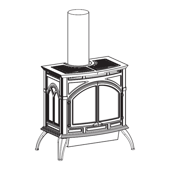
EMPIRE
EMPIRE
Comfort Systems
The Heritage Cast Iron Stoves
Installer: Leave this manual with the appli-
ance.
Consumer: Retain this manual for future refer-
ence.
WARNING: If the information in these instruc-
tions are not followed exactly, a fire or explosion
may result causing property damage, personal
injury or loss of life.
— Do not store or use gasoline or other
flammable vapors and liquids in the vicinity
of this or any other appliance.
— WHAT TO DO IF YOU SMELL GAS
•
Do not try to light any appliance.
•
Do not touch any electrical switch; do not
use any phone in your building.
•
Immediately call your gas supplier from a
neighbor's phone. Follow the gas suppli-
er's instructions.
•
If you cannot reach your gas supplier, call
the fire department.
— Installation and service must be performed
by a qualified installer, service agency or the
gas supplier.
INSTALLATION INSTRUCTIONS
OWNER'S MANUAL
This appliance may be installed in an aftermarket
permanently located, manufactured home (USA
only) or mobile home, where not prohibited by
local codes.
This appliance is only for use with the type of gas
indicated on the rating plate. This appliance is
not convertible for use with other gases, unless a
certified kit is used.
WARNING: Improper installation, adjustment,
alteration, service or maintenance can cause injury
or property damage. Refer to this manual. For assis-
tance or additional information consult a qualified
installer, service agency, or the gas supplier.
AND
CAST IRON
DIRECT VENT STOVE
MODELS:
DVP30CA30(B,F,M,S,W)N-1
DVP30CA30(B,F,M,S,W)P-1
GAS-FIRED
Page 1
Advertisement
Table of Contents

Related Manuals for Empire Comfort Systems DVP30CA30B-N1


Summary of Contents for Empire Comfort Systems DVP30CA30B-N1
-
Page 1: Cast Iron
INSTALLATION INSTRUCTIONS EMPIRE EMPIRE OWNER'S MANUAL Comfort Systems The Heritage Cast Iron Stoves CAST IRON DIRECT VENT STOVE MODELS: DVP30CA30(B,F,M,S,W)N-1 DVP30CA30(B,F,M,S,W)P-1 GAS-FIRED Installer: Leave this manual with the appli- ance. Consumer: Retain this manual for future refer- ence. WARNING: If the information in these instruc- tions are not followed exactly, a fire or explosion... -
Page 2: Table Of Contents
TABLE OF CONTENTS SECTION PAGE Important Safety Information ....................3 Safety Information for Users of LP-Gas ................4 Requirements for Massachusetts ..................5 Introduction .......................... 6 Specifications ........................7 Gas Supply ........................... 8 Clearances ........................9 - 10 Venting Fireplace ........................ 11 Restrictor Plate Installation .................... -
Page 3: Important Safety Information
• Keep burner and control compartment clean. glass frame assembly from Empire. See parts list on Page 30 for ordering. • Vent cap is hot while fireplace is in operation. -
Page 4: Safety Information For Users Of Lp-Gas
SAFETY INFORMATION FOR USERS OF LP-GAS Propane (LP-Gas) is a flammable gas which can cause fires by point with the members of your household. Someday when and explosions. In its natural state, propane is odorless and there may not be a minute to lose, everyone's safety will depend colorless. -
Page 5: Requirements For Massachusetts
REQUIREMENTS FOR MASSACHUSETTS For all side wall horizontally vented gas fueled equipment 3. SIGNAGE. A metal or plastic identification plate shall be installed in every dwelling, building or structure used in permanently mounted to the exterior of the building at a whole or in part for residential purposes, including those minimum height of eight (8) feet above grade directly in owned or operated by the Commonwealth and where the... -
Page 6: Introduction
• Modification of the fireplace or direct vent system. or through a representative is engaged in and is responsible for (a) • Installation other than as instructed by Empire Comfort Systems, the installation or replacement of gas piping or (b) the connection, Inc. -
Page 7: Specifications
Floor to Center of 90° elbow with a 24" length of pipe 56 1/4" (1428 mm) 56 1/4" (1428 mm) (See Figure 5) Venting Accessories (Special Vent Kits - Simpson Duravent Can be purchased from Empire Comfort Systems Inc.) DVKHP Direct-Vent Kit for Horizontal Run (46DVA-24B, 46DVA-09B, 46DVA-08AB, 46DVA-DC, 46DVA-WT, 46DVA-HC,... -
Page 8: Gas Supply
GAS SUPPLY Installing a New Main Gas Cock Consult the current National Fuel Gas Code, ANSI Z223.1 CAN/ Each appliance should have its own manual gas cock. CGA-B149 (.1 or .2) installation code. A manual main gas cock should be located in the vicinity of the Recommended Gas Pipe Diameter unit. -
Page 9: Clearances
CLEARANCES In selecting a location for installation, it is necessary to provide 4” (102mm) HEATER CORNERS TO SIDE WALL adequate accessibility clearances for servicing and proper opera- tion. 10” (254mm) Locating and Venting the Direct Vent Fireplace Clearances: When facing the front of the direct vent fireplace the minimum clearances to combustible construction (material) are the following: Top of appliance (ceiling) -
Page 10: Clearances
CLEARANCES (cont.) Special Vent Systems The following vent systems are acceptable for use with the DVP30CA fireplace: Simpson Duravent® GS 4" - 6 5/8" American Metal® 4" - 6 5/8" 90° ELBOW *Selkirk Direct-Temp® 4" - 6 5/8" * Can not be used in side wall horizontal vent installations in the State of Massachusetts. -
Page 11: Venting Fireplace
VENTING FIREPLACE (cont.) Sidewall Venting HORIZONTAL RUN IN FEET The maximum vertical and horizontal distances are 25 feet and 12 1 2 3 4 5 6 7 8 9 10 11 12 13 14 feet, respectively. Vertical dimensions are based on top of fireplace to centerline of pipe. -
Page 12: Restrictor Plate Installation
RESTRICTOR PLATE INSTALLATION The restrictor plate is to be used only in a completely vertical vent installation. The restrictor plate can be used when the vertical vent rise is between 10 feet and 25 feet. In a vertical vent rise the rear (yellow) flames on the main burner can be reduced due to the drawing action from the flue exhaust pipe and the air inlet pipe. -
Page 13: Adjusting Air Shutter
ADJUSTING AIR SHUTTER The air shutter has been factory set to the optimum performance level for this appliance. LP air shutter is not adjustable. Remove cast iron top and carefully set aside. Remove cast iron front and carefully set aside. Carefully remove glass door. -
Page 14: Termination Clearances
TERMINATION CLEARANCES Termination clearance for buildings with combustible and noncombustible exteriors. Figure 14 Vertical Sidewall Installations Important! Minimum clearance between vent pipes and combustible Since it is very important that the venting system maintain its materials is one inch (1") (25 mm) on, bottom and sides and (2") balance between the combustion air intake and the flue gas exhaust, (51 mm) on top. -
Page 15: Vent Clearances
VENT CLEARANCES Figure 15 *Clearance above grade, veranda, porch, deck or balcony Clearance to non-mechanical air supply inlet to building [*12 inches (304.8 mm) minimum] or the combustion air inlet to any other appliance [*12 inches (304.8 mm) minimum for appliances ≤ 100,000 Btuh Clearance to window or door that may be opened [*9 inches (30 kW) (228.6 mm) minimum for appliances <... -
Page 16: Vent System Identification
MAXIMUM OF TWO 90° ELBOWS 45° ELBOW ROOF FLASHING 90° ELBOW Special Venting Components (Simpson Duravent) See Empire Comfort Systems Inc. Retail Price List for Simpson Duravent part numbers and pricing. CEILING FIRESTOP WALL STRAP PIPE LENGTH (24” MINIMUM) Figure 16... -
Page 17: Framing And Finishing
FRAMING AND FINISHING Installing Support Brackets (Figure 18) A horizontal pipe support MUST BE used for each 3 feet of horizontal run. The pipe supports should be placed around 6 5/8 inch diameter pipe and nailed in place to framing members. There MUST BE a 2 inch clearance to combustibles above 6 5/8 inch diameter pipe and elbows and 1 inch clearance on both sides and bottom of 6-5/8 inch to combustibles on all horizontal pipe sections and elbows. -
Page 18: Horizontal Termination
FRAMING AND FINISHING (continued) Figure 21 Figure 22 HORIZONTAL TERMINATION Attach and secure the termination to the last section of horizontal venting by sliding cap over the last section of horizontal venting to ensure proper location. NOTE: Termination cap should pass through the wall firestop from the exterior of the building. -
Page 19: Vertical Termination
VERTICAL TERMINATION Vertical Terminations (Figures 24, 25, and 26) When terminating the vent cap near an exterior wall or overhang, Locate and mark the center point of the venting pipe. Using a nail maintain minimum clearances as shown in Figure 24. on the underside of the roof and drive this nail through this center General Maintenance point. - Page 20 VERTICAL TERMINATION (continued) Installing Support Brackets NOTE: When installing this vent system in a chase, it is always A horizontal pipe support MUST BE used for each 3 feet of horizontal good building practice to insulate the chase as you would the run.
-
Page 21: Log Placement
LOG PLACEMENT Remove cast iron top and carefully set aside. LEFT TWIG RIGHT TWIG Remove cast iron front and carefully set aside. Lower valve cover on firebox. Release two door latches at bottom of firebox. Grasp bottom of glass frame, lift glass frame upward in order to release glass frame from lip on top of firebox. -
Page 22: Operating Guidelines
OPERATING GUIDELINES Before operating this heater, please review the safety warnings Standing Pilot Operation pages at the beginning of this manual and those precautions and 1. Follow the SAFETY and LIGHTING INSTRUCTIONS for warnings listed below. standing pilot controls found in this manual and on labels found attached to the appliance. -
Page 23: Lighting Instructions
LIGHTING INSTRUCTIONS FOR YOUR SAFETY READ BEFORE LIGHTING WARNING: If you do not follow these instructions exactly, a fire or explosion may result causing property damage, personal injury or loss of life. A. This appliance has a pilot which must be lighted by •... -
Page 24: Pilot Flame Characteristics
PILOT FLAME CHARACTERISTICS Figure 30 shows a correct pilot flame pattern. The correct flame will be blue and will extend beyond the thermocouple and thermopile. The flame will surround the thermocouple and thermopile just below the tip. A slight yellow flame may occur where the pilot flame and main burner flame meet. -
Page 25: Main Burner Flame Characteristics
MAIN BURNER FLAME CHARACTERISTICS Figure 31 shows a correct main burner flame pattern. Figure 32 Cleaning the Log Set and Firebox shows an incorrect main burner flame pattern. Do NOT handle these logs with your bare hands. Always wear gloves to prevent skin irritation. During the annual inspection and If main burner flame pattern is incorrect, as shown in Figure 32: maintenance appointment, the service person should clean dust, lint, •... -
Page 26: Wiring
WIRING DVP30C ON/OFF/REMOTE Switch desired, turn the ON/OFF/REMOTE switch on wire channel from DVP30C is equipped with an ON/OFF/REMOTE switch which the REMOTE position to the ON position. is located on the wire channel located on the top, left side of 1. -
Page 27: Wiring
WIRING (continued) Wiring Diagram Figure 34 24032-2-1008 Page 27... -
Page 28: Maintenance
General Glass Information LATCH GLASS FRAME Only glass approved for use in Empire Comfort Systems Inc. fireplaces WITH 2 GLASS FRAME may be used for replacement. The glass replacement should be done by a CLAMPS licensed or qualified service person. -
Page 29: Troubleshooting
TROUBLESHOOTING With proper installation and maintenance, your new Direct Vent Fireplace should provide years of trouble-free service. If you do experience a problem, refer to the Trouble Shooting Guide below. This guide will assist a qualified service person in the diagnosis of problems and the corrective action to be taken. -
Page 30: Firebox Parts List
Do not order bolts, screws, washers or nuts. They are standard hardware items and can be purchased at any local hardware store. Shipments contingent upon strikes, fires and all causes beyond our control. Empire Comfort Systems, Inc. Nine Eighteen Freeburg Ave. Belleville, Illinois 62222-0529 Page 30... -
Page 31: Firebox Parts View
PARTS VIEW 21 22 24032-2-1008 Page 31... -
Page 32: Casting Parts List
CASTING PARTS LIST PLEASE NOTE: When ordering parts, it is very important that part number and description of part coincide. INDEX NO. PART NO. DESCRIPTION INDEX NO. PART NO. DESCRIPTION PORCELAIN BLACK COMMON PARTS R-9671 INSERT TAB (4 REQUIRED) R-9570 TOP INSERT - RIGHT R-9569 TOP INSERT - LEFT... -
Page 33: Casting Parts View
CASTING PARTS VIEW 24032-2-1008 Page 33... -
Page 34: Accessory Side Shelves
ACCESSORY SIDE SHELVES INSTALLATION INSTRUCTIONS Installing Accessory Side Shelves: Remove cast iron or stone inlay inserts from casting top and carefully set them aside. Remove cast iron top from stove and place upside down on a flat, soft smooth surface to avoid damage. Remove (4) ¼-20 hex head bolts from the outer edges of cast iron top. -
Page 35: Optional Blower Installation Instructions
OPTIONAL BLOWER INSTALLATION INSTRUCTIONS Installing Optional CIB-3 Blower 8. Attach 1/4" push-on terminal from black wire to the OFF Loosen, but do not remove, four (4) hex-head screws located (middle) tab on the switch. on the exterior, bottom of the appliance. 9. - Page 36 OPTIONAL BLOWER INSTALLATION INSTRUCTIONS Cleaning CAUTION: Label all wires prior to disconnection when servicing The blower wheel will collect lint and could require cleaning once controls. Wiring errors can cause improper and dangerous a year. If the air output decreases or the noise level increases, it operation.
-
Page 37: How To Order Repair Parts
Do not order bolts, screws, washers or nuts. They are standard hardware items and can be purchased at any local hardware store. Shipments contingent upon strikes, fires and all causes beyond our control. Empire Comfort Systems Inc. Nine Eighteen Freeburg Ave. Belleville, Illinois 62222-0529 SERVICE NOTES... -
Page 38: Service Notes
SERVICE NOTES Page 38 24032-2-1008... -
Page 39: Quick Reference
Web Site: www.empirecomfort.com Empire Comfort Systems EMPIRE EMPIRE 918 Freeburg Avenue Belleville, Illinois 62220-2623 Comfort Systems The Heritage Cast Iron Stoves GAS-FIRED Models: DVP30CA30B, DVP30CA30F, DVP30CA30S, DVP30CA30W DVP30CB30B, DVP30CB30F, DVP30CB30S, DVP30CB30W Specifications Model DVP30C(A,B)30(B,F,S,W) Input BTU/HR (KW/H) Maximum 30,000 (9.3) 32,000 (9.3) - Page 40 Empire Comfort Systems Inc. EMPIRE EMPIRE 918 Freeburg Ave. Belleville, IL 62220 If you have a general question about our products, please e-mail us at info@empirecomfort.com. If you have a service or repair question, please contact your dealer. Comfort Systems www.empirecomfort.com...
Need help?
Do you have a question about the DVP30CA30B-N1 and is the answer not in the manual?
Questions and answers