Table of Contents
Advertisement
Quick Links
INSTALLATION & OPERATING
Versa™
Spa
Heater
Model 055B
WARNING: If the information in these instructions are not followed exactly, a fire or
explosion may result causing property damage, personal injury or death
FOR YOUR SAFETY: Do not store or use gasoline or other flammable vapors and
liquids or other combustible materials in the vicinity of this or any other appliance. To
do so may result in an explosion or fire.
WHAT TO DO IF YOU SMELL GAS:
• Do not try to light any appliance.
• Do not touch any electrical switch; do not use any phone in your building.
• Immediately call your gas supplier from a neighbor's phone. Follow the gas
supplier's instructions.
• If you cannot reach your gas supplier, call the fire department.
Installation and service must be performed by a qualified installer, service agency or
the gas supplier.
This manual should be maintained in legible condition and kept adjacent to the heater or in another safe place for
future reference.
CATALOG NO. 6100.52W
INSTRUCTIONS
Effective: 05-23-11
Replaces: 01-21-10
.
P/N 240428 Rev. 24
Advertisement
Table of Contents

Summary of Contents for versa 055B
- Page 1 INSTRUCTIONS Versa™ Heater Model 055B WARNING: If the information in these instructions are not followed exactly, a fire or explosion may result causing property damage, personal injury or death FOR YOUR SAFETY: Do not store or use gasoline or other flammable vapors and liquids or other combustible materials in the vicinity of this or any other appliance.
- Page 2 Rev. 24 reflects the following: Changes to: Water Chemistry (Table A) on page 5, Wiring Diagram on page 20.
-
Page 3: Table Of Contents
CONTENTS WARNINGS Clearances Pay Attention to These Terms Outdoor Heaters WATER CHEMISTRY Indoor Heaters OWNER'S OPERATING INSTRUC- Combustion Air TIONS (Indoor Units Only) Start-Up Procedures Vent Piping Water Temperature Safety Vent Terminal Assembly MAINTENANCE AND CARE PROCE- Gas Supply Connections DURES Plumbing for Water Connections Basic Tips if Heater Will Not Fire... -
Page 4: Warnings
WARNINGS - Pay Attention to These Terms Indicates the presence of immediate hazards which will cause severe DANGER: personal injury, death or substantial property damage if ignored. Indicates the presence of hazards or unsafe practices which could cause WARNING: severe personal injury, death or substantial property damage if ignored. Indicates the presence of hazards or unsafe practices which could cause CAUTION: minor personal injury or product or property damage if ignored. -
Page 5: Water Chemistry
WATER CHEMISTRY CAUTION: Free chlorine must not exceed 5 ppm which can damage the heater and void the warranty. NOTE: Corrosive water voids all warranties. • Occasional chemical shock dosing of the pool or spa water should not damage the heater providing the water is balanced. -
Page 6: Owner's Operating Instructions
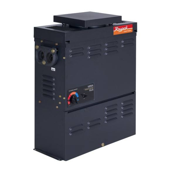
A yellow or "floating" flame indicates restricted air openings or incorrect orifice size. Should this occur, shut the heater off and contact your installer or gas Fig. 1: Versa Heater supplier. Water Pressure Switch A water pressure switch is provided in the heater to shut-off the burners in the event that water supply to the heater is interrupted. - Page 7 CAUTION: Propane is heavier than air and will settle on the ground. Since propane can accumulate in confined areas, extra care should be exercised when lighting propane heaters. LIGHTING INSTRUCTIONS AND SHUT-OFF PROCEDURES MANUALLY LIGHTED PILOTS (MILLIVOLT SYSTEM) A. This appliance has a pilot that must be lighted by *If you cannot reach your gas supplier, call the hand.
- Page 8 CAUTION: Propane is heavier than air and will settle on the ground. Since propane can accumulate in confined areas, extra care should be exercised when lighting propane heaters. OPERATING INSTRUCTIONS AND SHUT-OFF PROCEDURES AUTOMATICALLY LIGHTED PILOTS (ELECTRONIC IGNITION SYSTEMS) A. This appliance is equipped with an ignition *If you cannot reach your gas supplier, call the device which automatically lights the pilot.
-
Page 9: Water Temperature Safety
MAINTENANCE AND valve when water flow to the heater is interrupted. Otherwise, rapid and severe heater damage will likely CARE PROCEDURES occur. (The water pressure switch should be checked and adjusted for proper operation by a qualified serv- ice person at the time of installation and periodically To be followed one month after start-up and then semi- checked thereafter. -
Page 10: Pool & Spa Water Chemistry
If you have electrical power, check the following: water below 50°F can seriously damage the heater, and will void the warranty. 1. The time clock must be moved to the "ON" posi- tion. For cold climate areas please follow the winterizing procedures listed below. -
Page 11: General Specifications
Millivolt heaters contain a self- to the area adjacent to the appliance or to the generating electrical system operating between .25 structure. -
Page 12: Indoor Installation
Indoor Installation Outdoor Installation Min. Clearance from Min. Clearance from Heater Side Heater Side Combustible Surfaces Combustible Surfaces Top* (Drafthood) 35” Top* (Stackless Top) Unobstructed Vent 6” Back 2” Back 2” Right Side 6” Right Side 6” Left Side 6” Left Side 6”... -
Page 13: Outdoor Heaters
Indoor Heaters from or one (1) foot above any door, window or gravi- ty inlet to a building. The top surface of the heater shall be at least three (3) feet above any forced air inlet, or The design is also certified for indoor installation when intake ducts located within ten (10) feet horizontally. -
Page 14: Vent Piping
Vent Terminal Assembly Vent Piping Outdoor WARNING: Indoor boilers require a drafthood that must be connected to a vent pipe and properly 1. Remove the (4) screws which fasten jacket top to vented to the outside. Failure to follow this procedure heater. -
Page 15: Gas Supply Connections
12" WC and a maximum of 13" WC for propane. DRAFT HOOD 1/2” 3/4” Model 055B HEATER Natural Gas, 1000 BTU/FT .60 specific gravity @ 0.5” WC pressure drop Propane Gas, 2500 BTU/FT 1.53 specific gravity @ 0.5”... -
Page 16: Plumbing For Water Connections
Plumbing for Water Connections Location The VERSA heater requires water flow and positive pressure to fire and operate properly. It must therefore be installed downstream of the discharge side of the filter pump. A typical installation is plumbed as follows: 1. -
Page 17: Flow Rates
Flow Rates Automatic Chlorinators and Chemical Feeders Pipe Size Min. gpm Max. gpm 1-1/4” All chemicals must be introduced and completely dilut- ed into the pool or spa water before being circulated 1-1/2” through the heater. Do not place chlorine tablets or bromine sticks in the skimmer. -
Page 18: Electrical Wiring
External Auxiliary Bypass Valve NOTE: To avoid water damage or scalding due to (Where Required) valve operation, drain pipe must be connected to valve outlet and run to a safe place of discharge. Drain pipe must be the same size as the valve An auxiliary bypass valve should be used when flow discharge connection throughout its entire length rates exceed 60 gpm (usually a high performance... - Page 19 240V ATMOSPHERIC HEATER BLACK BLACK SUPPLY SIDE HEATER 4 WIRES Robertshaw Intermittent GREEN GREEN Ignition Device Honeywell Intermittent WHITE Ignition Device Fig. 21: 240V Wiring Fig. 19: Intermittent Ignition Devices For 120 V input power to the unit, connect the black CAUTION: Heater must be electrically grounded wire to the “L1”, or hot leg, of the power supply.
-
Page 20: Wiring Diagram-Millivolt Units With Mechanical Thermostat
Wiring Diagram—Millivolt Units with Mechanical Thermostat... -
Page 21: Wiring Diagram-Iid Units
Wiring Diagram—IID Units... -
Page 22: Service
SERVICE The thermostat is fitted with a means of limiting the upper temperature limit below the maximum level. The knob stop adjustment ring illustrated above is Controls/Adjustments/ adjustable by loosening the set screw, rotating the Replacements knobstop ring to the desired location and retightening the set screw. -
Page 23: Pressure Switch
Pressure Switch NOTE: If heater is installed outside of the limits shown, a flow switch must be used in place of the The pressure switch, or heater actuator, ensures that pressure switch when mounted and wired adjacent the heater operates only when the filter pump is in to the heater. -
Page 24: Burner Tray Removal
Main Burner and Orifice Removal NOTE: An erratic high limit is often characteristic of internal heat exchanger problem, e.g. scale build-up, 1. Remove burner tray. (See Burner Tray Removal U.G. operation. Refer to Troubleshooting section. procedure). 2. Remove screws and burner hold-down bracket. High Limit Removal NOTE: If the heat exchanger is sooted badly, the 1. -
Page 25: Heat Exchanger Removal
Heat Exchanger Removal 1. Shut water, gas, and electricity off, close valves and relieve pressure. 2. Drain heat exchanger. 3. Loosen and remove flange bolts. 4. Remove flange and inlet/outlet pipes from the header. Remove drain valve from rear header. 5. - Page 26 U.G. U.G. Retainer Shield Spring Outlet Inlet Inlet/Outlet Header Fig. 31: Unitherm Governor Location To test the operation of the Unitherm Governor, place in hot water (over 110°F) and watch for movement against spring. If there is no movement, replace unit.
-
Page 27: Troubleshooting
TROUBLESHOOTING These instructions are primarily intended for use by qualified personnel specifically trained and experienced in the installation of this type of heating equipment and related system components. Installation and service personnel may be required by some states to be licensed. Persons not qualified shall not attempt to install this equipment nor attempt repairs according to these instructions. - Page 28 ... . replace. U.G. not functioning...... Replace if no movement when heated. Leaking at well Overacid........Replace well and maintain water chemistry properly. Leaking at heat exchanger Overacid........Replace heat exchanger and maintain chemistry properly.
- Page 29 WARNING HIGH VOLTAGE ELECTRICAL - IID For qualified Technicians ONLY NOTE: Some heaters may be equipped with Intermittent Pilot System an ignition module that shuts off pilot gas if TROUBLESHOOTING HONEYWELL S8600 pilot fails to light. To reset, interrupt power to heater.
- Page 30 ELECTRICAL - IID, SOLID STATE THERMOSTAT If the pool/spa/hot tub water is too cold, troubleshoot the system as follows: Check voltage at 24 V terminals. VOLTAGE BETWEEN 21.5-28.5 V. VOLTAGE OUTSIDE RANGE 21.5-28.5 V. Set control to max. temperature. After 2-3 Check transformer, 120 V supply, correct as cycles, check water temperature.
-
Page 31: Replacement Parts List
REPLACEMENT PARTS serial number, model number, etc., and shipped to the Company freight prepaid. LIST If determined defective by the Company and within warranty, the part will be returned in kind or equal sub- In order to receive the correct part it is important that stitution, freight collect. - Page 32 10-H 12-H 13-H 14-H 11-H Fig # 240654 11-P HONEYWELL MILLIVOLT PILOT HONEYWELL IID PILOT 12-P 13-P 14-P 15-P 14-P Fig # 8133 Fig # 8132...
- Page 33 CALL PREMIUM DESCRIPTION BRONZE BURNER TRAY Burner Tray w/Burners (Sea Level)* 004688F Burner 301210/4 Burner Orifice Nat. #52 (Sea Level)* 350081F/4 Burner Orifice Pro. #62 (Sea Level)* 350086F/4 CONTROLS High Limit 135 F 600889B High Limit 140 F 600890B Thermostat Control MV (Mechanical) 003346F Thermostat Control MV (Solid State) 005391F...
- Page 34 CALL PREMIUM DESCRIPTION BRONZE PILOT Pilot Nat. MV 600525B Pilot Pro. MV 600575B Pilot Nat. IID 002003F Pilot Pro. IID 002003F Pilot Orifice Nat. MV 003901F Pilot Orifice Pro. MV 003902F Pilot Orifice Nat. IID 003903F Pilot Orifice Pro. IID 004308F Pilot Generator MV 600019B...