Table of Contents
Advertisement
Quick Links
Advertisement
Chapters
Table of Contents

Summary of Contents for Zhejiang Qianjiang Motorcycle RKV 200
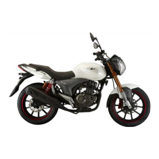
- Page 1 RKV 200 Motorcycle Service Manual...
-
Page 2: Table Of Contents
ZHEJIANG QIANJIANG MOTORCYCLE CO.LTD. Content Content ......................錯誤! 尚未定義書籤。 Preface ....................錯誤! 尚未定義書籤。 Service Data ..........................6 Inspection/Adjustment ......................47 Inspection and maintenance of electrical system ................61 Ⅰ Battery/Charging System ......................63 1.1 Service Data ........................63 1.2 Fault Diagnosis ........................ 64 1.3 Battery .......................... - Page 3 5.3 Front Hydraulic Brake...................... 92 5.4 Rear Hydraulic Brake ....................... 94 Ⅵ Motorcycle Exterior ................錯誤! 尚未定義書籤。 7.1 Service data ................... 錯誤! 尚未定義書籤。 7.2 Fault Diagnosis ................錯誤! 尚未定義書籤。 7.3 Front Wheel ................... 錯誤! 尚未定義書籤。 7.4Steering Handlebar ................. 錯誤! 尚未定義書籤。 7.5 Front Fork ..................錯誤! 尚未定義書籤。 Ⅷ...
- Page 4 14.2 Fault Diagnosis ................錯誤! 尚未定義書籤。 14.3 Crankcase ..................錯誤! 尚未定義書籤。 14.4 Gearshift Mechanism ..............錯誤! 尚未定義書籤。 14.5 Crankshaft Connecting Rod Assembly ........錯誤! 尚未定義書籤。 14.6 Gearbox Assembly ..............錯誤! 尚未定義書籤。 Exhaust System Inspection and Maintenance ........錯誤! 尚未定義書籤。 ⅩⅦ Emission Control System ..............錯誤! 尚未定義書籤。 15.1 Emission Control System Guarantee...........
-
Page 5: Preface
If patterns or structures of the motorcycles change, or differences exist between pictures, drawings, instructions or others and physical products, please take the later as the standard. The product is subject to change without further notice. ZHEJIANG QIANJIANG MOTORCYCLE CO.LTD... -
Page 6: Service Data
Service Data General Safety Maintenance Regulation Specification Sheet Fault Diagnosis General Safety Carbon monoxide (CO) When it is necessary to start the engine, please make sure the workplace is well ventilated. You shall never run the engine in an enclosed place. Attention Gas exhausted from the motorcycle contains toxic carbon monoxide, which may lead to loss of consciousness and even death. - Page 7 Maintenance Regulations While repairing and servicing, try to use tools of metric system as possible as you can. Incorrect tools may damage the motorcycle. Before take down or open protecting plate for maintenance work, please clean the dirt on external surface of the component or the assembly to prevent the dirt from falling into the engine, chassis or braking system.
- Page 8 Length of bolts and screws are different for assemblies and protecting plates. They shall be installed at correct positions. If confused, just put the bolt inside the hole and see if it matches. Fill lubricating grease into the groove during oil seal installation. Check if the oil seal is smooth and if it is possible to be damaged when installed.
- Page 9 Slack cable implies potential safety hazard on electrics. Check the next cable when the cable is clamped to ensure electric safety; Cable clamp shall not be bent towards solder joint; Tie the cable at appointed position; Don’t lay the cable at the end of frame or at the closed angle; Don’t lay the cable at the tip of a bolt or screw;...
-
Page 10: Important Notes
Important Notes 1.Please use spare parts manufactured by Zhejiang Qianjiang Motorcycle Co., Ltd. Components that cannot comply with designed specifications of Zhejiang Qianjiang Motorcycle Co., Ltd. may result in damage on the engine. 2.Only metric tools can be used for maintenance work. Metric bolts, nuts and screws cannot be exchanged with inch fasteners. -
Page 11: Special Tools
6.After assembly, check if all the components are correctly installed and can work properly. 7. Remove dirt and oil before measurement; apply recommended lubricant at lubricating positions at assembly. 8. When the engine and transmission system are disassembled/assembled and needed to be stored for a long time, please apply lubricant on the surface of the components to avoid rust and dust deposition. - Page 12 Figure 1-3 Figure 1-4 Figure 1-5 Figure 1-6 Figure 1-7 Figure 1-8 Figure Figure 1-10 ① Handle...
- Page 13 ① Pliers ② Figure 1-11 Figure 1-12 Piston Figure 1-13 Figure 1-14 Figure 1-15 Figure 1-16 Figure 1-17 Figure 1-18...
- Page 14 Figure 1-19 Figure 1-20 Figure 1-21 Figure 1-22 Figure 1-23 Figure 1-24 2.Toes for chassis overhaul Common and special tools, as well as their pictures for chassis component assembly and disassembly are listed in Table1-25 and 1-26. Table1-25 Name Remarks Torque wrench Figure1-27 Allen wrench...
- Page 15 Figure 1-27 Figure 1-28 Figure 1-29 Figure 1-30 Figure 1-31 Figure 1-32 Figure 1-33 Figure 1-34 Figure 1-35 Figure 1-36 (2)Special tools for chassis overhaul:front fork seal driver...
- Page 16 Figure 1-37 (3)Steering nut wrench Figure 1-38 3.Tools for electrical components Special tools and their pictures for electrical component test are listed in Table1-39 and Table 1-40. Table 1-39 Name Remarks Multimeter Figure1-41 Ignition tester Figure1-42 Continued Table 1-40 Figure 1-41 Figure 1-42...
- Page 17 Specifications (QJ200-2A) Model QJ200-2A Engine type QJ168FML -B Overall Length(mm) 2080 Fuel RQ-90 Number of Overall Width(mm) cylinders 1060 Bore*stroke 68×55 Overall height(mm) Total 1350 200cc Wheelbase(mm) Displacement Front Starting mode Electric axle Weight (kg) Rear Air cooling and oil Cooling mode (Curb weight)...
-
Page 19: Fault Diagnosis
Fault Diagnosis Engine will not start or is hard to start. Diagnosis procedures Engine will not start or is hard to start Check ignition system Remove the spark plug and check if electrodes of the plug are connected by carbon. Perform spark-over test Clean deposited carbon Spark is weak between electrodes or no spark at all. - Page 20 Check leakage 1. Check if breather on external connection parts the fuel tank cap is of engine; 2.Check valve clogged; 2. Check if timing; 3. Check if valve fuel filter fuel clearance is too small; 4. switch are clogged; 3. Check tightness between Check if fuel switch Remove...
- Page 21 Symptom: Engine Overheats Diagnosis procedures Engine Overheats Check for improper operaton method 1. Check if gasoline grade being used is too Check cooling system low or the gasoline has been stored for a too long time; 2. Check if engine runs at a high speed for a very long time or overloaded Oil cooling the engine Air cooling the engine...
- Page 22 Remove the spark plug and check Clutch slips Check pump works color of skirt section of insulating part and other abnormalities to judge normally; 2 Check if thermostat Handle it as Item 1.7. works perfectly; 3. Check if oil pipe mixture ratio of combustible gas in the system is clogged.
- Page 23 Symptom: Engine lacks power Diagnosis procedures Engine lacks power Lift it with main stand to have the wheels off the ground. Rotate wheels by hands. Wheels rotate freely. Wheels rotate inflexibly. Check tire pressure 1. Check braking drag; 2. Check if bearing of wheels are over worn or injured;...
- Page 24 Symptom: Poor idle speed of engine Diagnosis procedures Poor idle speed Engine has no idle speed. Higher idle speed Unsteady idle speed Pull throttle valve of carburetor by hand Use an ignition timing lamp to Check compression pressure in cylinder and see if it is completely closed.
- Page 25 Symptom: Too much fuel consumption by the engine Diagnosis procedures Too much fuel consumption Check operation method Lift it by main stand, rotate wheels by hands 1. Check if motorcycle is driven overspeed or not at economical speed or driven at low gear; 2. Check if gasoline grade being Wheels rotate inflexibly.
- Page 26 Symptom: Clutch slips Diagnosis procedures Clutch slips Manually controlled wet multi-plate clutch slips Automatic centrifugal shoe-type clutch slips Check if braking shoe of shoe-type clutch is contaminated by oil Check if clearance of clutch handle bar is within 10mm~20mm. Check if braking shoe Clean greasy Check if throttle control cable can...
- Page 27 Symptom: 4-stroke engine exhaust muffler gives off blue-white smoke Diagnosis procedures 4-stroke engine exhaust muffler gives off blue-white smoke Check if engine oil level in the crankcase exceeds the upper limit line Start engine and run it at high speed; screw off Too much engine oil in the crankcase, bleed surplus oil oil ruler and check if oil filler smokes.
- Page 28 Incomplete separation of clutch Check if clearance of clutch handle bar is within 10mm~20mm. Re-adjust Check if adjusting screw for clutch push rod is properly adjusted Check if elasticity of clutch spring is even. Re-adjust Check if splines on clutch active and drive hubs are worn into zigzag form Replace the whole set of clutch spring.
- Page 29 Difficult gearshift on transmission Start engine and check if idle is too high. Readjust Check if the operation is harmonious at gearshift. Check if cluth is completely separated. Improve operation method. Check if gearshift box is distorted and shift lever is deformed or overworn. 1.
- Page 30 Symptom: Jumps of gear on the transmission Diagnosis procedures Jumps of gear on transmission Check if spring of position wheel is broken or of insufficient elasticity. Replace Disassemble crankcase and check if meshing depth of each gear meets requirement. Enough meshing depth Insufficient meshing depth Check if meshing end of cam pawl on end face of meshing Check if shift fork is overworn.
- Page 31 Symptom: Drum-type brake fails Diagnosis procedures Drum-type brake fails. Check if clearance of brake handle bar is within 10mm~20mm or clearance of brake pedal within 20mm ~ 30mm range. Re-adjust Separate cable of brake rocker arm from brake control cable. Move rocker arm by hands. Brake rocker rotates...
- Page 32 Symptom: Battery can not be charged Diagnosis procedures Battery can not be charged. Disconnect connectors of magneto lead wire tied to the cables of the whole motorcycle. Measure with an Ohmmer resistance between output wires from charging coil. Resistance is less than standard. Resistance meets the standard.
- Page 33 Symptom: Battery cannot be fully charged Diagnosis procedures Battery cannot be fully charged. Check if braking lamp is always on. Set ignition switch to “OFF” position, disconnect negative wire from battery, and then put Adjust or replace braking lamp switch. negative probe of ammeter onto the negative terminal and positive probe on the negative wire to check current leakage.
- Page 34 Symptom: Starter motor does not run Diagnosis procedures Starter motor does not run. Turn on ignition switch; press horn button or slide turn signal lamp switch. Electric horn does not sound or sound Electric horn sounds loudly. weakly. Turn signal lamp is dim. Turn signal lamp is bright.
- Page 35 Disassemble starter motor and Coil in starter coil Check wiring in electrical Contact of stater make the following inspections: broken starter control system relay is burnt or 1.Check if the carbon brush is shorted. injured. over worn; 2. Check if carbon brush spring is broken or weak.
- Page 36 Symptom: Starter motor runs weakly Diagnosis procedures Starter motor runs weakly. Turn on ignition switch; press horn button or slide turn on signal lamp switch. Electric horn does not sound or sound Electric horn sounds loudly. weakly. Turn signal lamp is bright. Battery is low or the lead wire Check if the lead wire connector from starter relay connector connected with battery is...
- Page 37 Symptom: All the lights are not on Diagnosis procedures All the lights are not on AC power supplied lighting system DC power supplied lighting system Separate conductors of lead wire bundle of magneto from the cables of the whole vehicle. Check if there is power Press horn button or slide turn signal light.
- Page 38 Replace headlamp bulb and Check if there is power output from power check other bulbs one by one. input wire of light switch by lamp test Use a piece of wire to short circuit power line and Wiring from magneto or ignition output line of lighting switch.
- Page 39 Symptom: Light bulb is apt be burnt Diagnosis procedures Light bulb is apt to be burnt. Turn on ignition switch; press horn button or slide turn signal lamp switch. Electric horn does not sound or sound Electric horn sounds loudly. hoarse.
- Page 40 Symptom: Headlamp is dim. Diagnosis procedures Headlamp is dim AC power supplied lighting system DC power supplied lighting system Separate conductors of lead wire bundle of magnet from Turn on ignition switch; press horn button cables of the whole vehicle. Measure and check with an or slide turn signal lamp switch.
- Page 41 Check if power of bulb in the lighting Replace the bulb. system is up to the requirement. 1. Check if headlamp switch Replace bulb. and contact in the switch is poorly contacted; 2. Check if connectors and earthing wire poorly contacted.
- Page 42 Symptom: Turn signal lamp is off. Diagnosis procedures Turn signal lamp is not on. All the turn signal lamps are not on. Some of the turn signal lamps on one All the turn signal lamps on side is not on. one side are not on.
- Page 43 Separate connectors of turn signal lamp switch and use Scintillator is damaged. a piece of wire to short circuit respectively power input line of the switch and power lines output to left and right turn signal lamps. Turn signal lamp is on after short circuit. Turn signal lamp is still off after short circuit.
- Page 44 Symptom: Electric horn mutes. Diagnosis procedures...
- Page 45 Electric horn mutes. Turn on ignition switch; slide turn signal lamp switch and check. Turn signal lamp is not lit or dim. Turn signal lamp shines brightly. Battery is low or the wire from battery Power supply from battery is normal. to ignition switch is broken or shorted.
- Page 46 Symptom: Brake lamp does not work. Diagnosis procedures Brake lamp does not work. Take down cover of brake lamp and check if bulb is burnt. Replace bulb Use a piece of wire to short circuit two terminals of brake lamp switch or plugs of two hatching lines. Lamp is not lit after short circuit.
-
Page 47: Inspection/Adjustment
Inspection/Adjustment Basic data Compression pressure of cylinder Periodic maintenance schedule chart Engine oil Engine oil/filter Replacement of engine oil Steering stem bearing and handlebar fixation Drive chain slackness Throttle cable adjustment Front/rear brake clearance Air cleaner Headlamp Spark plug Clutch Battery Front/rear suspension system... -
Page 48: Specifications
Specifications Engine Idle speed 1400±100r/min Spark plug clearance 0.6-0.7mm Spark plug type CR9E Combustion chamber Spherical Ignition time(angle of before top dead center) 1500RPM:15°CA/4000RPM:35°CA Frame Clearance of front brake handle 10-20mm Clearance of rear brake pedal 20-30mm Specification Tire Pressure Front wheel 100/80-17 190±10kPa Pneumatic pressure unit of tire:Kpa... - Page 49 Periodic maintenance schedule chart Mileage and Every Every Every Every Every interval Every 1000K 3000 6000K 12000 14500 300 KM Tools Items three Twelve Fifteen Vehicle month months months months months Air cleaner Common tool Common tool Gasoline filter Common tool Engine oil filter Engine oil Replacement Replace every 5000KM.
-
Page 50: Engine Oil Level
Valve Feeler gauge Expected Inspection Ignition system—-perform maintenance inspection on obvious and continuous ignition malfunctions, engine on fire, overheated back burning and others. Carbon deposit removal—-obvious underpower, get rid of carbon deposited at cylinder head, piston head and air exhaust system. Piston and cylinder—-When cylinder is over worn or stuck, please replace it. -
Page 51: Throttle Cable Adjustment
When the engine oil is completely drained, put back cleaned drain plug and sealing ring. Refill engine oil to specified level. Check if there is engine oil leakage. Start the engine and run the engine on idle for a few minutes. Check engine oil level again. -
Page 52: Spark Plug
* Attention While removing filter element of air cleaner, please do not run the engine, in case unfiltered air comes into the engine, which may result in fast wear of some components or damage the engine. On the other hand, rotation of engine without filter element may affect the carburetor and the carburetor will not work normally afterwards, which may result in overheated engine. - Page 53 Battery Removal Remove the seat cushion and take down the right protecting plate. Remove the battery from the battery case(1). Disconnect the battery negative (-) lead wire first and then the positive (+) lead wire. Take out the battery. Warning! During positive lead wire disconnection, be sure to prevent the tools being used from touching the frame;...
-
Page 54: Idle Speed Adjustment
Charging Connection method: Positive pole of battery charger is connected to battery positive lead wire; Negative pole of battery charger is connected to battery negative lead wire. Warning! • Battery shall be away from fire source. • Shut off charger switch first before or after charging in case sparks may be generated at connection parts, which may result in explosion. -
Page 55: Engine Oil
Stop the engine and connect the timing lamp to lead wire of spark plug. Remove timing hole cap. Start engine and idle it. Inspect ignition timing. If symbol “F” aligns with the mark on the right crankcase, it indicates that the ignition timing is correct. -
Page 56: Engine Oil Replacement
premature component wear. Refilling engine oil of poor quality or different types or brands will reduce lubrication effects. When the engine stops, clean dust on the oil level indicator on the right side cover with a piece of clean cloth. Stand the engine on a horizontal plane and check oil level in the oil level indicator. - Page 57 Adjust drive chain slackness: Screw off rear shaft nut and locknuts of adjusters on both drive chains. Rotate uniformly both adjusters till the drive chains gain normal slackness. * Attention Do not install new drive chains onto worn sprockets or install worn drive chains onto the new sprockets.
- Page 58 Headlamp Remove the locknuts of headlamp . Take down the headlamp. Pull out connector of headlamp holder and remove the reflector. Release the circlip and take out lamp holder. * Attention When the bulb is lit, keep you hands and inflammable materials some distance away from it.
-
Page 59: Front Suspension
Front/rear suspension system Front suspension Grasp the front brake handle and compress upward and downward the front shock absorber to check its actuation. Check if the front shock absorber leaks oil and if the components are loosened. Rear Suspension Compress upward and downward the rear shock absorber to check its actuation. -
Page 60: Tire Specifications
Wheel rim/tire Check if there is crack, nails and similar sharp objects, and other injuries on the tyres. * Attention Measure cold inflation tire pressure. Specified air pressure Unit:Kpa Tire specifications Tyre pressure Front tire 100/80-17 190±10kPa QJ200-2A Rear tire 130/70-17 210±10kPa Tire Specifications... -
Page 61: Inspection And Maintenance Of Electrical System
Inspection and maintenance of electrical system Tightening torque table for fasteners used in electric system Fastening positions and names of fasteners Tightening torque(N·m) Starter motor clutch cover bolt Starter motor clutch locknut Rectifier bolt High-voltage coil pinch bolt Flywheel locknut Vehicle block protecting plate bolt... -
Page 62: Charging System
Charging system Charging System 1.Variable frequency scintillator 2. Ignitor 3. Battery 4. Voltage regulator High-voltage ignition coil 6. Electric horn 7. Rectifier... -
Page 63: Ⅰ Battery/Charging System
Ⅰ Battery/Charging System Service Data-----------------------1.1 Fault diagnosis----------------------1. Battery-------------------------------1. Charging system--------------------1.4 Voltage/current regulator--------1.5 Magneto charging coil-------------1.6 Removal of magneto-------------1.7 1.1 Service Data Precautions on operation * Attentions 1. The battery can be charged and discharged, and used repeatedly. If a battery is laid aside after discharging, its service life will be shortened and its performance is degraded. -
Page 64: Fault Diagnosis
8. Quick charging is forbidden except in emergency. 9. During quick charging, the battery must be removed from the motorcycle first and then be charged. 10. While battery is exchanged, please do not use liquid-feeding battery. 11. A voltmeter shall be employed to check the state of charged battery. Service Data Item Specification... -
Page 65: Battery
1.3 Battery 1.3.1 Battery Removal Take down the right protecting plate . Disconnect the battery negative lead wire first and then the positive lead wire. Remove the battery breather. Remove battery mounting bracket. Take out the battery. Warning! During positive lead wire disconnection, be sure to prevent the tools being used from touching the frame;... -
Page 66: Charging System
* Attention • Battery quick charging is not recommended except in case of emergency. • After charging, measure the battery voltage in 30minutes’ time. Charging current: Standard: 0.3A Quick charging: 3.0A Charging time: Standard: 10-15hours Quick charging: 30minutes Charging completed: open circuit voltage: higher than 12.8V 1.4 Charging system 1.4.1 Short circuit test Disconnect the grounding wire from the battery and use a voltmeter to connect battery negative... -
Page 67: Magneto Charging Coil
Disconnect the 6P plug on the voltage-current regulator. Check continuity between main wiring terminals in the following way: Item (wire color) Judgment Between battery (red) and There is battery ground of vehicle block voltage. Between ground wire (black) There is a lead wire. and ground of vehicle block Between charging coil No power flowing... -
Page 68: Magneto Removal
1.7 Magneto Removal 1.7.1 Removal Remove vehicle block protecting plate. Remove protecting plate of engine on the left side. Remove flywheel locknut. Use a flywheel remover to take down the flywheel. Remove the fixation key. Disconnect lead-wire connector of magneto. Disconnect magneto stator. - Page 69 ** Attention There is magnetism on the inner surface of flywheel, and make sure there is no bolt. Fix the flywheel using a universal non-adjustable spanner and then tighten the locknut. Torque value: 9.0 N·m Install protecting plate on the left side.
- Page 70 Ignition System Ignition System 1.Variable frequency scintillator 2. Ignitor 3. Battery 4. Voltage regulator High-voltage ignition coil 6. Electric horn 7. Rectifier...
-
Page 71: Ⅱ Ignition System
Ⅱ Ignition System Service CDI assembly----------------------2.4 data------------------------------2.1 Fault Ignition diagnosis---------------------------2. coil--------------------------2.5 Ignition system Trigger--------------------------------2. inspection-------------2.3 2.1 Service Data Precautions on operation 1. Ignition system inspection: please perform inspection in accordance with the sequence listed in the fault diagnosis table. 2. Ignition system uses electronic-type automatic timing device, which is solidified in the CDI assembly, so ignition time adjustment is unnecessary. -
Page 72: Fault Diagnosis
0.35±15%Ω Primary coil Ignition coil impedance value With spark plug cap 8-11KΩ Secondary (20℃) Without spark plug 4.2±15%KΩ coil Impedance value of trigger(20℃) 100-200Ω Impedance value of charging coil(20℃) 600-800Ω Ignition coil primary peak voltage 95-400V Higher than Trigger voltage 1.7V Tools Accessories for the voltage with maximum range... -
Page 73: Ignition System Inspection
①Defective ignition coil. No high-voltage power supply or ②Defective charging coil. high voltage power is sporadic. ①Inner impedance is too low. Use appointed tester to test. ②Crankshaft rpm is too low. High-voltage power supply is too ③Tester is disturbed (it is normal when more than one time’s low. -
Page 74: Cdi Assembly
*Attention Please do not touch the metal parts of testing probe with your fingers while measuring voltage, or you will be shocked. Please take care. 2.3.3 Trigger * Attention Inspect when spark plug is installed on the cylinder head and compression pressure is normal. Disconnect connector 4P and 2P from CDI assembly. -
Page 75: Cdi Assembly
2.4 CDI Assembly 2.4.1 System Inspection System inspection. Remove CDI assembly and check components related to ignition system at wiring terminal. 2.4.2 Inspection Remove CDI assembly and check if connectors are loosened or corrosive. Item Measured terminal Standard Value(20℃) Main switch Red—Red/White On continuity when main switch is “OFF”. -
Page 76: Trigger
Measure impedance between terminals of primary coil. Standard value:0.4Ω±10%(20℃) Impedance value within the range is good. Impedance value “∞” indicates broken wire inside the coil. The coil shall be replaced. 2.5.3 Secondary coil Provided with a spark plug. Measure impedance between lead-wire side of spark plug cap and terminal. -
Page 77: Starting System
Starting System Starting Schematic Diagram 1.Variable frequency scintillator 2. Ignitor 3. Battery 4. Voltage regulator High-voltage ignition coil 6. Electric horn 7. Rectifier... -
Page 78: Ⅲ Starting System
Ⅲ Starting System Service Data-----------3.1 Fault diagnosis--------3.2 Starter motor-----------3.3 Starter relay------------3.4 3.1 Service Data Precautions on operation Starter motor removal can be performed on the engine. Starter clutch removal refers to removal instruction. Basic data Item Standard Service Limit Length of starter motor 12.5mm 8.5mm electric carbon brush... -
Page 79: Fault Diagnosis
3.2 Fault Diagnosis Stator motor cannot run Stator motor runs weakly Starter motor rotates but the engine does not •Broken Fuse •Low battery •Defective starter clutch •Low battery •Poor connecting wire contact •Starter motor counter-rotate •Defective ignition switch •Stator motor gear stuck by •Low battery •Defective starter clutch foreign substances... - Page 80 assemblies. Confirm uncontinuity of armature shaft among surfaces of commutator. Inspect for continuity of starter motor housing. Confirm incontinuity between conducting terminal and starter motor housing. Inspect continuity between conducting terminal and brush. Replace it with a new one if abnormality exits. Inspect carbon brush holder for continuity.
-
Page 81: Starter Relay
3.4 Starter Relay 3.4.1 Actuation Inspection Take down the protecting plate of vehicle block. When the ignition switch is set at “ON” position, press starter motor and a “Click” sound can be heard. “Click” sound indicates normal. No sound: • Check starter relay voltage. •... - Page 82 Bulbs/Switches/Instruments Headlamp certification No.: E4 0014699 Front turn signal lamp certification No.: E4 50R 001732 Tail lamp certification No.: E4 50R 0014700 Rear turn signal lamp certification No.: E4 50R 001732 Side reflector certification No.: E11 020612 Rear license plate lamp certification No.:...
-
Page 83: Bulbs/Switches/Instruments
Bulbs/Switches/Instruments Instrument----------------4. Service data----------------------------------------4.1 Fault Ignition diagnosis------------------------------------4. switch-----------4.7 Headlamp bulb Electric replacement---------------4.3 horn-------------4.8 Front turn signal lamp bulb Handle switch-----------4.9 replacement-------------4.4 Tail lamp bulb replacement ----------------4.5 4.1 Service Data Precautions on operation Remove switches from the motorcycle and perform continuity test. All the plastic connectors have pawls on them. -
Page 84: Fault Diagnosis
4.2 Fault Diagnosis “ON” lamp of ignition switch is not lit. • Defective bulb. • Defective switch. • Poor contact of connector or broken wire. • Low battery power or no voltage. 4.3 Headlamp bulb replacement 4.3.1 Removal Screw off with a wrench locknut of headlamp and take down the headlamp. -
Page 85: Front Turn Signal Lamp Bulb Replacement
4.4 Front turn signal lamp bulb replacement 4.4.1 Removal Disconnect wire to turn signal lamp. Screw off self-tapping screw on the turn signal lamp. Remove the bulb socket from the lamp. Remove the bulb from lamp adapter. 4.4.2 Installation Install the bulb in the reverse order of removal. 4.5 Tail lamp bulb replacement 4.5.1 Removal Screw off the two bolts. -
Page 86: Instrument
4.5.3.1 Removal Screw off mounting bolts on the tail lamp hood. Remove tail lamp hood(1)so that tail lamp bulb can be removed. Remove the tail lamp bulb from lamp adapter. 4.5.3.2 Installation Install the tail lamp bulb in the reverse order of removal. 4.6 Instrument Remove rear mirror. -
Page 87: Electric Horn
Remove the front protecting plate. Unscrew the mounting bolt and take down the main switch holder. Remove the mounting bolt and replace the main switch. 4.8 Electric horn Inspection Disconnect wire to the electric horn. Connect lead wire of horn with the battery. When the electric horn sounds, it indicates the horn is in good condition 4.9 Handle switch... -
Page 88: Chassis Inspection And Maintenance
Chassis Inspection and Maintenance Tightening Torque of Fasteners on Chassis Fastening positions and names of fasteners Tightening Torque(N·m) Oil pump assembly mounting bolt Front brake cylinder assembly mounting bolt 22-29 Rear brake rocker arm mounting bolt Rear shaft locknut 85-98 Steering handle welding assembly mounting bolt 22-29 Front wheel shaft locknut... -
Page 89: Front Hydraulic Brake
Front Hydraulic Brake Front brake disc diameter:260mm Front brake disc thickness:4.0mm Service limit:3.0 Thickness of friction lining:4mm Service limit:3.0mm Mounting torque for Bolt 3 in the diagram:5-9 N·m Mounting torque for Bolt 6 in the diagram:5-9 N·m Clearance of brake handle: 10-20mm 1 Oil pump block assembly 2 Front brake handle... -
Page 90: Rear Hydraulic Brake
Rear Hydraulic Brake Mounting torque for Nut 17 in the diagram: 5-9 N·m Rear brake drum ID:130 Service limit:131 Thickness of friction lining:4.0mm Service limit:3.0mm Mounting torque for Bolt 6 in the diagram:22-29 N·m Mounting torque for Bolt 22 in the diagram:5-9 N·m 2 Bushing Ⅱ... -
Page 91: Ⅴ Braking System
Ⅴ Braking System Maintenance instruction-------------------5.1 Fault diagnosis-------------------------------5.2 Front hydraulic brake-----------------------5.3 Rear hydraulic brake-----------------------5.4 5.1 Maintenance Instructions Precautions on operation * Attention • Please do not contaminate braking assembly with oil while assembly or disassembly. • Please use specified detergent to clean the braking assembly, or it may reduce braking performance. * Please check braking system before driving your motorcycle.* 5.1.1 Specifications Item... -
Page 92: Fault Diagnosis
5.2 Fault Diagnosis Braking System Poor braking performance Brake drags or tight handle 1. Improper brake adjustment 1. Improper brake adjustment 2. Worn friction lining assembly 2. Worn friction lining assembly 3. Friction lining assembly improperly installed 3. Friction lining assembly improperly installed 4. - Page 93 5.3.2 Inspection Check if the friction linings are worn out. Replace them if necessary. Measure friction lining and hydraulic brake disc and record the maximum values. Specifications φ260mm QJ200-2A Front hydraulic brake disc diameter Front hydraulic brake disc thickness 4.0mm * Attention •...
- Page 94 Do not contaminate friction linings with oil. If a friction lining is polluted by oil, clean it with brake cleaner. *Attention A contaminated friction lining will weaken braking performance. 5.4 Rear Hydraulic Brake 5.4.1 Removal Remove seat cushion assembly protecting plate assembly. Remove the engine assembly, air filter assembly and muffler assembly.
- Page 95 Measure thickness of braking shoes and hydraulic brake discs. If the braking shoes are contaminated by oil or their thickness is smaller than the service limit, replace them. Measurement of hydraulic brake discs can be performed on the motorcycle and removal is not required. Note: Braking shoes shall be replaced in pairs.
- Page 96 Exterior *Attention Do not damage the exterior during disassembly. Do not damage falcula on the exterior during disassembly. Align insert plates and covers on the exterior with their slots. Correctly install falculas on each position during assembly. Do not damage auxiliaries during installation of the exterior. 1.
- Page 97 VI. Motorcycle exterior Disassemble the motorcycle body in the following sequence. Seat cushion assembly→ Left guard component→ Right guard component→ LR tail cap→ RR tail cap→ Left pedal→ ↓ Right pedal→ Reinforcing plate, front mud fender→ Front mud fender→ Rear mud fender component→...
-
Page 98: Front Wheel
Front wheel Rim runout limit: Vertical: 2.0mm Horizontal: 2.0mm Wearing limit: 1.0mm 1 Front wheel shaft 2 Gear housing assembly 3 Rolling bearing 4 Intermediate sleeve, front wheel 5 Gear housing oil seal component 6 Front wheel disk 7 Big gear drive vane 8 Oil seal component, front wheel 9 Left bearing sleeve, front wheel 10 Front braking disk 11 Mounting bolt, hydraulic braking disk 12 Right lining, front wheel 13 Sub-assembly, front wheel 14 Vacuum tyre 100/80-17 15 Inflating valve Z2-01-1/direct... -
Page 99: Steering Handlebar
Steering handlebar 1 RR mirror assembly 2 LR mirror assembly 3 Handlebar stop 4 Right handlebar component 5 Right combined switch 6 Welded component, steering handlebar 7 Left combined switch 8 Left steering handlebar sleeve 9 Left handle component 10 Left handle 11 Handle fixing bolt 12 Bolt M6×25 13 Bolt M6×20 14 Fixed cover 15 Adjusting screw 16 Adjusting nut 17 Left handle base 18 Clutch wire sleeve 19 Socket head cap screw M6×35 20 Check valve flexible wire clamp 21 Bolt M6×25 22 Nut M6 23 Mounting screw, brake pedal 24 Spring washer 10 25 Lining 26 Welded component, brake pedal 27 Brake pedal tensioning spring 28 Valve steel cable component 29... -
Page 100: Front Fork
Front fork 1 Steering shaft rod nut 2 Dust shield 3 Upper steel bowel, upper bearing 4 Steel ball 3/16’’ 5 Lower steel bowel, upper bearing 6 Upper steel bowel, lower bearing 7 Steel ball 1/4’’ 8 Lower steel bowel, lower bearing 9 Lower bracket, lamp 10 Cable clamp 11 Socket head cap screw M8×30 12 Upper base, steering handlebar... - Page 101 VII. Front wheel/Front suspension Service Data-----------------------------7. 1 Fault Diagnosis-------------------------7. 2 Front Wheel-----------------------------7. 3 Steering Handlebar---------------------7. 4 Front Fork-------------------------------7. 5 7. 1 Service Data Precautions Prior to disassembly of the front wheel, use a jack to support against bottom of the motorcycle, and it is important that the front wheels must not rotate reversely when they keep away from the ground.
- Page 102 The handlebar bearing is faculty. The handlebar bearing is damaged. Pressure within the tyre is too low. Air leaks from the tyre. 7. 2. 2 Direction not steady The handlebar bearing is damaged. Pressure within the tyre is insufficient. Front fork is bent and its bearing is bent. Front wheel tyre is subjected deformation and the tyre is not aligned.
- Page 103 QJ200-2A front wheel. 7. 3. 2 Check 7. 3. 2. 1Check of wheel shaft bending Place the wheel shaft onto a V-shaped base, and the measure eccentricity with a micrometer gauge. Allowable limit: replacing is required in case of exceeding 0. 2mm. 7.
- Page 104 7. 3. 4 Installation Installation must be initiated in the reverse sequence of disassembly. Attention: Lubricate the front wheel shaft, gear housing component, oil seal, bearing sleeve, rolling bearing (6301) and intermediate sleeve. The recommended lubricant is calcium-base grease. Install the front wheel shaft (1), front wheel, gear housing component (2) and nut M12Χ1.25.
- Page 105 *Note: See P96 of this manual for disassembly of QJ200-2A steering handlebar. It should be installed by reversing the sequence of disassembly. Fixing bolt, welded component, steering handlebar Torque force value22-29 N·m 7. 5 Front fork 7. 5. 1 Disassembly Support the main stand of the motorcycle.
- Page 106 Clean the opening on the body opening with dust rag. The steel bowels of the upper and lower bearings are removed by means of special tool. 7. 5. 3 Installation Apply grease onto the steel bowel of bottom bearing confirm the number of steel balls (23 balls). The steering handlebar is non-turnable (to prevent steel balls from falling) and then install the steering handle.
-
Page 107: Rear Wheel
Rear wheel Tyre dimensions: vacuum tyre 130/70-17 Rim runout limit: Vertical: 2.0mm Horizontal: 2.0mm Wearing limit: 1.0mm Rear hydraulic braking disk diameter: 240mm Torque force value of bolt 12 in the figure: 85-98 N·m 1 Self-locking nut M14×1.5 2 Right oil seal assembly of front wheel 3 Rolling bearing 6202-2RS 4 Mounting bolt M6×16 of hydraulic braking disk 5 Rear braking disk 6 Rolling bearing 6302-2RS 7 Rear wheel disk 8 Bearing sleeve 9 Washer φ16×φ32×2 10 Damper, rear wheel 11 Left bearing sleeve component of rear wheel 12 Rear wheel shaft M14×1.5×292 13 Sub-assembly of rear wheel 14 Vacuum tyre 15 Inflating valve... -
Page 108: Rear Shock Absorber
Rear shock absorber 1 Domed nut M10×1. 25 2 Mounting gasket, rear shock absorber 3 Rear shock absorber component 4 Washer 12 Bolt M10×1.25×40... -
Page 109: Rear Swing Arm
Rear swing arm Side play limit (for swingarm opening end): 1.0mm Torque force value of nut 1 in the figure: 70-83 N·m 1 Self-locking nut M14×1.5 2 Mounting washer, rear swingarm 3 Intermediate bearing sleeve 4 Mounting shaft, rear swingarm 5 Chain protective pad 6 Rear swingarm welding set, 7 Chain regulator 8 Screw M5×12 9 Sleeve 2 10 Holddown plate, chain regulator 11 Nut M8 12 Rear hydraulic brake cable clamp 13 Screw M6×12 14 Intermediate sleeve 15 Lining of rear swingarm 16 Dust shield component... -
Page 110: Chain Drive Assembly
Chain drive assembly Torque force value of bolt 11 in the figure:5-9 N·m Looseness drive chain: 20-40mm Torque force value of bolt 1 in the figure: 37-244 N·m 1 Mounting bolt M10×1. 25×38, sprocket 2 Sprocket hub 3 Chain driving sleeve 4 Rolling bearing 6204-2RS 5 Dust shield component 6 Toothed sprocket, sprocket 40 7 Anti-loosening locking pad, sprocket... - Page 111 VIII. Rear wheel/Rear suspension Service Data---------------------------------------8. 1 Fault Diagnosis------------------------------------8. 2 Rear Wheel-----------------------------------------8. 3 Rear Shock Absorber/Rear Swingarm----------8. 4 Chain Drive Assembly----------------------------8. 5 8. 1 Service Data Precautions Any grease spot is not allowed on the hydraulic braking disk and friction disc. Reference Item Standard value (mm)
- Page 112 Motorcycle frame or swingarm is bent. 8. 2. 2 Wheel rotating without flexibility Brake regulates incorrectly. Rear wheel bearing is worn. Driving chain is too tightened. 8. 2. 3 Bad braking performances Brake regulates incorrectly. Brake friction disc is worn. Hydraulic braking disk is worn.
- Page 113 8. 3. 2 Check 8. 3. 2. 1 Check of wheel disk wobbling Turn the rear wheel manually and measure eccentricity with a micrometer gauge. Allowable limit Longitudinal direction: replacing in case of exceeding 2. 0mm Horizontal direction: replacing in case of exceeding 2. 0mm If the rear wheel wobbling exceeds the allowable limit, the rear wheel bearing is loosened, consequently the rear wheel wobbling.
- Page 114 8. 4 Rear shock absorber/rear swingarm 8. 4. 1 Dismantling rear shock absorber Remove the sealing cover. Remove the upper and lower fixing bolts (5) and nut (1) from the rear shock absorber. Remove the rear shock absorber. 8. 4. 2 Check of rear shock absorber Check rear shock absorber rod, and if it is bent or damaged, replace the rear shock absorber component.
- Page 115 Note: See P101 for details of removal and installation. 8. 4. 5 Check of rear swingarm Check the mounting shaft of rear swingarm and turn the shaft or measure it with a micrometer gauge after it is placed onto a flat surface. If the shaft is bent, replace it. *Attention Do not attempt to straighten bent shaft.
- Page 116 8. 5. 2. Check Measure length of 10 links , and if it does not meet specified value, replace the driving chain. Limit length of the 10 links is 127mm. *Attention: Measurement shall be made only after the chain is straightened manually. Measurement shall cover from link roller ①...
- Page 117 Check rear hydraulic brake, and if any crack or wearing is found, replace it. Check rear wheel damping sleeve, and if it is worn or damaged, replace it. Check wheel bearing, and if bearing clearance is found within the hub or the wheel cannot rotate in a balanced manner, replace it.
- Page 118 Seat cushion Notes: To dismantle gasoline tank, turn the fuel switch to OFF. Torque force value of bolt 2 in the figure: 22-29 N·m Torque force value of bolt 5 in the figure: 22-29 N·m 1 Cushion assembly 2 Bolt M8×20 3 RR rack, rear carrier screw I4 5 RR rack (flat black B4) 6 LR rack...
-
Page 119: Fuel Tank
Fuel tank Gasoline capacity: 17±0. 5L Torque force value of screw 13 in the figure: 5-9 N·m Torque force value of nut 6 in the figure: 5-9 N·m Notes: To dismantle gasoline tank, turn the fuel switch to OFF. 1 Tank cover support component 2 Tank body component 3 Tank mounting pad 4 Fuel sensor component 5 Sensor rubber gasket 6 Nut M6 7 Tank switch component 8 Sealing gasket, tank cover 9 Tank mounting pad 10 Tank mounting shaft sleeve 11 Rubber sleeve 12 Tank mounting gasket 13 Bolt... -
Page 120: Fuel Tank/Seat Cushion
IX. Fuel tank/Seat cushion Service Data-----------------------9. 1 Fault Diagnosis--------------------9. 2 Fuel Tank/Seat Cushion----------9. 3 9. 1 Service Data Precautions The dismantling site shall keep away from source of spark. To dismantle gasoline tank, turn the fuel switch to OFF. During assembly, tighten the bolt and nut to specified torque force value. After assembly, check if all parts are installed correctly and operated correctly. - Page 121 9. 3 Fuel tank/Seat cushion 9. 3. 1 Disassembly Dismantle the right and left guards. Insert the ignition key into the seat lock, turn the key clockwise and open the lock. Insert the ignition key into the seat lock, turn the key clockwise and open the lock.
- Page 122 Maintenance and check of engine Fastener Torque Force Value Table Fastening position and fastener description Fastening torque (Nm) Cylinder head nut 24~30 Cylinder head cover bolt 9~12 Cylinder double end studs 24~30 Flywheel locking bolt 40~55 Valve clearance adjustment nut 9~12 Gear shift locator bolt 9~12...
- Page 123 X. Lubricating system Service Data------------------10. 1 Fault Diagnosis---------------10. 2 Engine Oil Pump-------------10. 3 10. 1 Service Data Function of lubricating system: engine lubricating system is to supply lubrication oil to friction surface of engine elements, turning the dry friction on the surface into liquid friction between lubrication oil particles, thus mitigating part wearing, cooling down parts with high thermal load, absorbing impact from bearing and the elements and consequently reducing noises, increasing tightness between cylinder ring and wall, and cleaning and taking away foreign matters from...
- Page 124 10. 2Fault Diagnosis Gasoline volume decreases Engine damaged Gasoline is consumed naturally. No or too low oil pressure Oil leakage Oil circuit clogged.
- Page 125 10. 3 Engine oil pump 10. 3. 1 Disassembly Remove the right cover, unscrew the pump fixing screw after engine oil filter is removed, and then remove the pump body, driving gear and pump shaft. Engine oil filter Engine oil pump body Remove screws.
- Page 126 Check radial clearance between inner and outer rotors Testing gauge Allowable limit: 0. 25mm. Check clearance between outer rotor and pump base. Testing gauge Allowable limit: 0. 25mm. Check rotor face-to-face clearance Flat plate Allowable limit: 0. 15mm. Testing gauge...
- Page 127 10. 3. 2 Assembly of engine oil pump As shown in the following figure. Driving gear Engine oil Engine oil pump shaft Engine oil pump body Outer rotor Inner rotor pump base Attention: After these parts are combined into the pump, the inner and outer rotors must be free to rotate without jamming.
- Page 128 Swingarm Cam mechanism Piston Oil filter Cranksha Engine oil filtration net Engine oil pump...
-
Page 129: Disassembly Of Carburetor
XI. Carburetor Service Data--------------------------11. 1 Fault Diagnosis----------------------11. 2 Disassembly of carburetor---------11. 3 Installation of carburetor-----------11. 4 11. 1 Service Data Function of carburetor: It is a key part of engine fuel supply system, and its operation status has a direct bearing on operation stability, power and economic indexes of the engine. It atomizes a certain amount of gasoline into fine oil droplets and mixes these droplets with different amounts of air evenly, thus forming combustible mixed gas mist with different density depending on the needs of engine under different operating conditions and promptly supplying the gas to engine, ensuring... - Page 130 Needle valve locked Bad idle adjustment Bad oil surface adjustment Bad oil volume adjustment Idle system or power enrichment valve clogged. Too many fuels in engine Too thin mixed gas Too much oil and overflow Jet clogged Secondary air entering into fuel system Needle valve clogged Fuel degradation Too low oil level...
- Page 131 11. 3. 2 Decomposition of carburetor Remove the fixing plate of throttle cable. Take down the throttle valve bonnet, spring and throttle valve. Throttle valve Throttle valve cover Throttle cable fixing plate Spring Upper cover Screw Unscrew screws Plunger remove the upper cover. Take spring componen...
- Page 132 Remove the idling adjusting screws and their springs. Dismantle mixture screw and its spring. 11. 3. 4 Assembly and installation Assembly and installation are in the reverse sequence of disassembly. 11. 3. 4 Adjustment of carburetor Attention: The idling adjusting screws have been adjusted when the carburetor is delivered, so no adjustment is needed in general.
- Page 133 XII Cylinder head/Valve Service Data-----------------------------------12. 1 Fault Diagnosis--------------------------------12. 2 Cylinder Head----------------------------------12. 3 Inspection----------------------------------------12. 4 Valve Guide Replacement----------------------12. 5 Valve Race Fixing and Adjustment------------12. 6...
-
Page 134: Service Data
Installation-----------------------------------------12. 7 Adjustment of Valve Clearance-----------------12. 8 12. 1 Service Data Function of cylinder head: It is used to seal cylinder and form the combustion chamber along with the piston in order to withstand high-temperature and high-pressure combustible gas. Through the valve system, the cylinder head intakes and discharges gas. Precautions To ensure seal between the cylinder head and cylinder body, the head withstand large pre-tension force from bolt. -
Page 135: Cylinder Head
Air leakage from cylinder head gasket Too much accumulated carbon in combustion chamber Poor installation of spark plug 12. 3 Cylinder head 12. 3. 1 Disassembly Loosen the two fixing bolts and remove the cylinder head cover (swingarm and its shaft). Cylinder head cover Bolt Release the tightener, loosen the chain and unscrew cover nut to take down cam shaft bracket,... - Page 136 Measure outer diameter of swingarm shaft. Allowable limit: 11. 93mm Micrometer 千分尺 Measure inner diameter of swingarm hole. Allowable limit: 12. 05mm Clearance between swingarm hole and swingarm shaft Allowable limit:0. 075mm Tester Directly remove the cylinder head cover and compress the valve spring with the valve spring compression tool and remove the valve locking clamp.
-
Page 137: Inspection
12. 3. 2 Decomposition of valve Valve locking clamp Gasket Valve Spring disk Valve spring Valve oil seal 12. 4 Inspection Clear carbon accumulated on the cylinder cover. Measure flatness of the interfacing surface on the cover. Allowable limit: 0. 05mm If the flatness exceeds the allowable limit, place fine sands on a flat board, engage the interfacing surface with the board, and then grind in a “8”... - Page 138 Measure outer diameter of valve rod. Allowable limit: 4. 92mm for discharge and 4. 935 for intake Micrometer Check the valve guide. Prior to check, use a reamer to eliminate carbon accumulated within the guide. Attention: the reamer shall be turned clockwise and do not turn it counterclockwise. Reamer Measure inner diameters of valve guides.
-
Page 139: Valve Guide Replacement
Tester 12. 5 Valve guide replacement Attention: If clearance between the valve and its guide, replace the guide. After the guide is replaced, trim surface of the valve washer. Place the guide into the freezing chamber of electrical refrigerator for one-hour cooling. Heat the cylinder head to 100-150℃... -
Page 140: Valve Race Fixing And Adjustment
Reamer Clear carbon accumulated within the combustion chamber and valve, and thoroughly clean the intake and discharge valves. Check width of valve contact surface (valve race width). Allowable limit: Intake/discharge: 1. 3mm. Racer contact surface 12. 6 Valve race fixing and adjustment Use a 45°... - Page 141 Use a 32° cutter to clear 1/4 of external end of race. Use a 60° cutter to clear 1/4 of bottom of race. Remove the cutter and check the processed locations. Use a 45° trimming cutter to grind the race so that it meets the suitable width.
- Page 142 If the contact is higher part in the valve, use a 32° cutter to lower the race to its minimum height. High contact If the contact is lower part in the valve, use a 60° surface cutter to raise the race to its minimum height. 32°...
- Page 145 XIII Cylinder block and piston Service Data--------------------13. 1 Piston----------------------------13. 4 Fault Diagnosis-----------------13. 2 Installation----------------------13. 5 Cylinder block------------------13. 3 13. 1 Service Data Precautions All parts must be cleaned before being checked, and purged with high-pressure air. Function of cylinder block: It offers a space for gas compression, combustion and expansion, and guides in piston motion.
-
Page 146: Cylinder Block
13. 2Fault Diagnosis Low compression pressure White smoke from discharge duct Piston worn, burnt or broken Piston ring worn or damaged Cylinder and piston worn or damaged Cylinder and piston worn or damaged Gasket damaged and air leakage between crankcase and gas Too high compression pressure Abnormal noise from piston Too much accumulated carbon in... - Page 147 13. 4 Piston 13. 4. 1 Disassembly Remove the piston retaining ring. Attention: During removal, do not fall the retaining ring into crankcase. Take out the piston pin and remove the piston. Wrist pin 活塞销挡圈,活塞销 Remove the piston ring. Check piston, piston pin and piston ring. Attention: do not break or damage the piston ring.
- Page 148 Measure piston pin hole ID. Allowable limit: 16. 04mm. Tester Measure piston pin hole OD. Allowable limit: 15. 96mm Clearance between piston pin hole and piston pin Allowable limit: 0. 024mm 90° 11mm Measure piston OD. Attention: measurement is made at such position as to form 90°...
- Page 149 Measure the roundness of cylinder inner wall Upper (difference between X ID and Y ID). Allowable limit: 0. 05mm Middle Measure the cylindricality of cylinder inner wall (ID difference at the upper, middle and lower positions Lower between X and Y). Allowable limit: 0.
- Page 150 Clear all of gaskets attached on the crankcase. Attention: any foreign matter shall not fall into the crankcase. Install piston, piston pin and its retaining ring. Mark “IN” Attention: the mark “IN” at the piston top is installed facing the intake valve. 13.
- Page 151 14. 1 Service Data Function of crankcase: It is a bearing component in the engine. It is provided to support the crankshaft, clutch, gearbox, cylinder block and head, withstand impact from combustion and inertia force due to crankshaft connecting rod mechanism, and it also forms some enclosed spaces (oil-seal and gas-seal).
- Page 152 14. 2 Fault Diagnosis Low compression pressure Abnormal noise in the crankcase Crankcase air leakage Parts loosened or broken in crankcase Overheating engine Automatic engine shutdown Clutch sliding Clutch jammed Poor lubrication Failure to put into gear Difficulty in gear shifting Gear shifter broken or deformed Clutch disengaged incompletely Shifter guiding pin broken...
- Page 153 Use the electrical or pneumatic tool to loosen flywheel locking nut. Take out the flywheel component (including sprocket), and remove the idle gear of motor. Remove the gasket. Gasket Idle gear of motor Flywheel components Remove the gear display. Gear display 14.
- Page 154 14.4 Clutch 14.4.1 Dismounting Unscrew the five bolts in the pressure plate with the diagonal cross method. Dismount the clutch spring, pressure plate, thrust Bolt on separating disc washer, plane needle roller bearing and bearing support. Refer to the breakdown drawing for dismounted components.
- Page 155 14.4.2 Clutch disassembly 1 nut; 2 Phillips adjusting screw; 3 thrust washer; 4 plane needle roller bearing; 5 lock nut; 6 bearing support; 7 lock washer; 8 bolt assembly; 9 pressure plate; 10 clutch spring; 11 friction disc assembly; 12 driven friction disc assembly;...
- Page 156 Measure the free length of the pressure spring. Replace it if the limit is below 29.7 mm. Free length Measure the thickness of the friction disc with a vernier caliper. Thickness Replace it if the limit is below 2.6mm. Measure the flatness of the driven friction disc with a plug gauge.
- Page 157 Measure the thickness of the plane needle roller bearing. Replace it if the limit is below 1.8mm. Needle roller bearing Crank connecting rod combination and gearbox assembly Crank connecting rod combination Right crank case Locating pin Bolt Left crank case...
- Page 158 Gearshift drum Shifting fork Shift rail Principal shaft assembly Vice shaft assembly...
-
Page 159: Gearshift Mechanism
14.4 Gearshift Mechanism 14.4.1 Dismounting Dismount the gearshift combination. Dismount the upper baffle bolt, the upper baffle and gearshift ratchet wheel gear ring. Dismount the lower baffle bolt, the lower baffle and the ratchet wheel. Dismounted components are revealed in the dismantling drawing. - Page 160 Check the abrasion of the locating plate of the gearshift. Replace it if there is too much abrasion. Check if the gearshift shaft is bent. Replace it if it is excessively bent. Check the elasticity of the restoring spring. Replace Clutch drive wheel gear it if necessary.
-
Page 161: Crankshaft Connecting Rod Assembly
14.5 Crankshaft connecting rod assembly 14.5.1 Dismounting Remove the crankshaft connecting rod assembly from the right crank case. Note: do not damage the surface of the case. Plug gauge 14.5.2 Check Measure the clearance on the left and right side of the big end of the collecting rod. - Page 162 Check if the crank shaft is noisy or loose while restoring. Replace it if so. Crank shaft bearing Note: both the crank connecting rod and the gearshift mechanism are installed on the crank case. Draw out the shifting fork. Remove the gearshift drum. Remove the gearshift fork.
- Page 163 14.5.3 Check Measure the external diameter of the shifting fork. Allowable limit: 9.96mm. Micrometer Measure the inner diameter of the fork hole. Allowable limit: 10.05mm. Tester Measure the thickness of the shifting fork. Allowable limit: respectively 5.1mm and 5.35mm. Vernier caliper Measure the external diameter of the gearshift drum.
- Page 164 Principal shaft assembly 14.6 Gear box assembly Vice shaft Remove the principal shaft assembly. assembly Remove the vice shaft assembly. Dismantling drawing of the principal and vice shaft assemblies Principal shaft assembly Vice shaft assembly 1 plug; 2 shaft sleeve; 3 washer; 4 first gear wheel on the vice shaft; 5 needle roller bearing; 6 fifth gear wheel on the vice shaft; 7 spline washer;...
- Page 165 Check Check the abrasion of the wheel gear surface and the Wheel gear surface drive claw. Replace it if there is too much abrasion or damage. Drive claw Remove the bearing in the left crank case. Check possible damages on the bearing and the oil seal. Replace them if there are damages. Note: the removed bearing can not be used any more.
- Page 166 Bearing Principal and vice shaft assemblies Note: lubrication oil should be used on the wheel gears and shafts while assembling them. Ensure the wheel gear works normally after the completion of the assembling work. Note: the assembling work of the crank case should be done in the reverse order.
- Page 167 Exhaust System Inspection and Maintenance Muffler Torsion force of the locating bolt 5 in the connector of the muffler in the figure: 5-9N·m Torsion force of the protective shield 6 in the connector of the muffler in the figure: 5-9N·m 1 welded components on the muffler;...
-
Page 168: Emission Control System
ⅩⅦ Emission Control System Emission Control System Guarantee……………………………………...…...…..15.1 Periodical Maintenance Instructions/Ensuring Emissions Standards.………..……15.2 Mechanical Functions of Emission Control System……………………………….15.3 Solutions to the problem of idle exhaust exceeding specified value (four-stroke)...15.4 15.1 Emission Control System Guarantee 1. This emission control system is in accordance with the revised versions of the EU EC/97/24/5/I and 2003/77/EC B. - Page 169 This vehicle has passed strict inspection. It completely meets the emissions control standards. Due to the varying concrete conditions of use of the vehicles, we made the following inspection table for periodic emissions inspection. To ensure normal levels of emissions, the user should follow the specified intervals of maintenance, adjustment or repair.
- Page 170 15.4 Solutions to the problem of idle exhaust exceeding specified value (four- stroke) Implement periodic check (maintenance plan) Qualified Idling emissions measurement (Note 1) Qualified Carburetor adjustment (Note 2) Qualified Qualified & finished Dismount and clean the carburetor product (SJ, MJ, SAJ, MAJ and so on) Qualified Carburetor replacement Dismount and repair the engine...
- Page 171 Complete QJ200-2A Schematic Circuit Diagram...
Need help?
Do you have a question about the RKV 200 and is the answer not in the manual?
Questions and answers