Table of Contents
Advertisement
Advertisement
Table of Contents

Related Manuals for DaySequerra M3

Summary of Contents for DaySequerra M3
- Page 1 Multi-Tuner Monitor User Manual...
- Page 2 While the M3 has been designed to be straightforward to use, we do suggest that you spend a few minutes familiarizing yourself with the features and operational functions that are contained in this manual.
-
Page 3: Table Of Contents
Performance Loss Monitor User Settings One Year Warranty " " " All rights reserved DaySequerra Corp, Copyright 2011. All logos and trademark used herein are the property of their respective owners. Specifications subject to change. 3" M3.0 Revision B. M3#User#Manual#... -
Page 4: Important Safety Information
The DaySequerra M3 contains no user serviceable components inside the unit. Please contact DaySequerra for repair and upgrade information. In the event that your unit needs to be returned to the factory, contact us for a return authorization number. The tuner ID and firmware version is momentarily displayed at tuner start-up for your convenience. -
Page 5: M3 Key Features
M3"Key"Features THREE SEPARATE AM, FM AND HD RADIO™ TUNERS - dedicated vacuum florescent displays SEPARATE AM AND FM ANTENNA INPUTS – Industry standard 75-ohm “F” connectors DEDICATED HD LOCKED, MULTICAST AVAILABLE, DELAY SET AND TUNER ALARM STEREO ANALOG OUTPUTS – Balanced (+4dBm) for 100% analog modulation AES3 DIGITAL AUDIO OUTPUTS –... -
Page 6: Unpacking And Installing
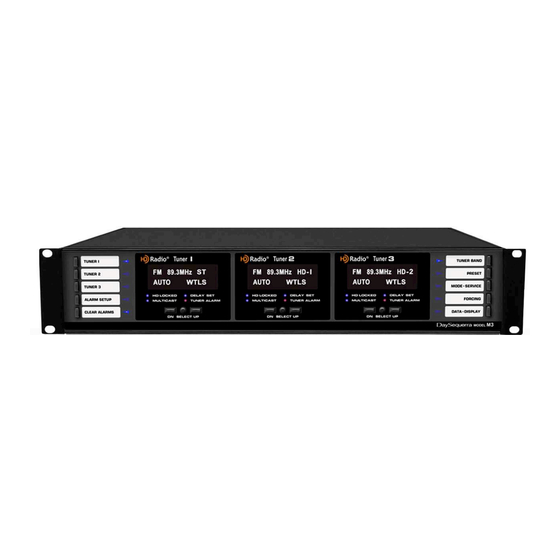
We strongly encourage you to save the shipping carton and shipping materials supplied with your M3. They are specially designed to properly protect your M3, and in the event that you need to return it for service, only these OEM shipping materials can ensure its safe return to our factory. - Page 7 TUNER ALARM – Red LED indicator identifies a detected alarm condition in any tuner module. It is solid when any alarm on the selected tuner has been enabled. When an alarm condition occurs, the tuner module’s LED flashes, the beeper beeps and the appropriate rear panel contact closes. M3 Front Panel Layout "" HEADPHONES.
- Page 8 PSD messages from an HD Radio broadcast for display on the second line of the VFD. Momentary push DATA - DISPLAY switch scrolls display through each RDS/RBDS and HD Radio PSD message data field, as described below. 8" M3#User#Manual#...
-
Page 9: Rear Panel Controls And Connectors
RJ-45 connector or ‘network port’ that will initially be used for re-programming the system processor. A 120/240VAC input voltage selector is located on the bottom of the unit directly underneath the power inlet. M3 Rear Panel Layout 9" M3#User#Manual#... -
Page 10: M3 Operating Description
M3 to be displayed for 3 seconds on Tuner 1’s VFD. If rear panel AC switch is turned off or if the power is momentarily interrupted, all tuner modules and M3 control/status returns to its previous state. - Page 11 MODE – SERVICE menu is active. In any active mode, second push of MODE – SERVICE at any time clears mode. Use the UP or DOWN switches to change the selection and press SELECT to enable the selection. 11" M3#User#Manual#...
-
Page 12: Sample Vfd Displays
ID Codes are 2-digit numerical values. Sample Broadcast SERVICE VFD Display Use UP, DOWN or SELECT to exit SERVICE display and return to MODE – SERVICE menu; • second push of MODE – SERVICE at any time clears mode. > 12" M3#User#Manual#... - Page 13 0-15. A value of 15 represents the highest audio quality. Momentary push of UP scrolls to next DIAGNOSTICS screen that can initiate Bit Error Rate • Mode. Push SELECT to enter Bit Error Rate Mode. < > 13" M3#User#Manual#...
- Page 14 Use the UP or DOWN switches to change the selection and then press SELECT to set 5kHz • IBOC filter ON or OFF permitting full 10kHz AM audio bandwidth. Exit the FORCING mode or FORCING menu at any time by pressing FORCING switch. 14" M3#User#Manual#...
- Page 15 In A-D SPLIT mode, the analog audio outputs have an analog audio signal in the left channel • and a digital audio signal in the right channel. Subsequent momentary push of FORCING switch turns FORCING mode and FORCING LED off. Default mode is off. 15" M3#User#Manual#...
- Page 16 < > The M3’s audio output can be set to automatically mute for received signals with RF signal strength less than 45dBf. The second DATA - DISPLAY menu field enables or disables this “Audio Muting” feature. UP or DN switches toggle the setting; pressing “SELECT” saves the setting and increments the menu to the next field.
- Page 17 VFD displays “NO” plus the data category, e.g., “NO RT DATA.” If “Scroll All Data” mode is enabled in DATA - DISPLAY menu, as described above, tuner displays each RBDS data field for approximately 5 seconds before scrolling to the next RBDS data field. 17" M3#User#Manual#...
-
Page 18: Performance Loss Monitor
Select “OFF” to set all alarms to off; select “SETUP” option to continue with alarm configuration menu. Use UP and DN switches to toggle the setting. Push “SELECT” switch to increment the menu to the next alarm function. • > < 18" M3#User#Manual#... - Page 19 Highlight desired “SET” or “OFF” option using UP and DN switches to toggle the • setting. Select “SET” to set this tuner alarm and continue with alarm configuration menu; select “OFF” to set this tuner alarm function to off. Push “SELECT” to continue. > < 19" M3#User#Manual#...
- Page 20 If “SET” is selected, submenu for “Alarm Delay” with “30”, “60”, “120” and “240” • second options is displayed next. Use UP and DN switches to toggle the setting and highlight the desired option. > < Push “SELECT” switch to save and increment the menu to the next alarm function. 20" M3#User#Manual#...
- Page 21 If two multicast programs are being broadcast and one is interrupted, the MC Available Loss alarm will not activate because of the remaining multicast program. MC Available Loss is an option only for an HD Radio FM broadcast. 21" M3#User#Manual#...
- Page 22 Use UP and DN switches to toggle the setting. < > Push “SELECT” to continue. The alarm configuration settings are saved in non-volatile memory. Activate Alarm - Activate tuner alarm conditions saved in configuration by holding the ALARM SETUP button for 5 seconds. 22" M3#User#Manual#...
-
Page 23: User Settings
User Settings Holding TUNER BAND switch during power on, will cause the M3 to enter User Settings mode. All of the tuner modules’ audio outputs are muted, all front panel controls and displays are disabled except for Tuner 1’s VFD, UP, DN and SELECT switches. -
Page 24: One Year Warranty
DaySequerra warrants this product to be free from defects in materials and workmanship to its original owner for one (1) year from the date of purchase. DaySequerra will repair or replace such product or part thereof that upon inspection by DaySequerra, is found to be defective in materials or workmanship subject to conditions contained herein.
Need help?
Do you have a question about the M3 and is the answer not in the manual?
Questions and answers