Table of Contents
Advertisement
Quick Links
TICO Series
THERMAL IMAGING CLIP-ON
OPERATOR'S MANUAL (TICO Series) REVISION 5 – SEP, 2014
o p e r a t o r ' s m a n u a l
Important Export Restrictions! Commodities, products,
technologies and services contained in this manual are
subject to one or more of the export control laws and
regulations of the U.S. Government and they fall under the
control jurisdiction of either the US Department of State or the
US BIS-Department of Commerce. It is unlawful and strictly
prohibited to export, or attempt to export or otherwise transfer
or sell any hardware or technical data or furnish any service to
any foreign person, whether abroad or in the United States, for
which a license or written approval of the U.S. Government is
required, without first obtaining the required license or written
approval from the Department of the U.S. Government having
jurisdiction. Diversion contrary to U.S. law is prohibited.
Advertisement
Table of Contents

Summary of Contents for American Technologies Network TICO series
- Page 1 TICO Series THERMAL IMAGING CLIP-ON OPERATOR’S MANUAL (TICO Series) REVISION 5 – SEP, 2014 o p e r a t o r ’ s m a n u a l Important Export Restrictions! Commodities, products, technologies and services contained in this manual are subject to one or more of the export control laws and regulations of the U.S.
- Page 2 Register your product warranty online at www.atncorp.com/warranty Manual (TICO Series) Revision 5 – September, 2014 The information in this manual furnished for information use only, is subject to change without notice, is not to be construed as a commitment by ATN Corp.
-
Page 3: Safety Summary
STUDY CAREFULLY THIS MANUAL BEFORE TURNING ON AND OPERATING THIS PRODUCT. CAUTIONS The TICO Series Thermal Imaging Clip-On are precision elec- tro-optical instruments and requires careful handling. To pro- vide safe use of the systems the following instructions should be observed: •... - Page 4 (such as the sun or a welding arc). If you do, you will damage the scope. WARNING Operating TICO Series outside of its specified operating tempera- ture range or voltage range can cause permanent damage and will void the warranty.
- Page 5 Observe battery manufacturer’s guidelines for safe handling and proper disposal of batteries. EQUIPMENT LIMITATIONS • The TICO Series detector spectral band (7 to 14 mkm) pro- vides a better penetration through smoke, smog, dust, water vapor etc. • Infrared radiation does not travel through glass and therefore the scope does not sense objects if they are behind a glass window.
-
Page 6: Table Of Contents
TABLE OF CONTENTS CHAPTER 1. INTRODUCTION ....1-1 1.1. General Information ....1-2 1.1.1. - Page 7 3.2.5. Brightness ......3-8 3.2.6. Zoom ......3-8 3.2.7.
-
Page 8: How To Use This Manual
HOW TO USE THIS MANUAL • Usage You must familiarize yourself with the entire manual before operat- ing the equipment. Read and follow all warning notices. • Manual Overview The table of contents includes the paragraph number, paragraph title, and page number. An index provides additional references to the subject contents. -
Page 9: Chapter 1. Introduction
CHAPTER 1 INTRODUCTION... -
Page 10: General Information
This manual contains instructions for use in operating and maintaining the TICO Thermal Imaging Clip-On. Throughout this manual, the TICO Series will be referred to as the scope or TICO. 1.1.2. REPORTS Reports from the user on recommendations for improvements are encouraged. - Page 11 3 YEAR PRODUCT WARRANTY This product is guaranteed to be free from manufacturing defects in material and workmanship under normal use for a period of 3 (three) years from the date of purchase. In addition the uncooled thermal sensor array carries a 10 year warranty.
- Page 12 or consequential damages, including, but not limited to, lost income, lost reve- nue, or lost profit, whether such damages were foreseeable or not at the time of purchase, and whether or not such damages arise out of a breach of warranty, a breach of agreement, negligence, strict liability or any other theory of liability.
-
Page 13: Description And Data
1.2. DESCRIPTION AND DATA 1.2.1. DESCRIPTION a. Purpose Representing the latest advancement in thermal imaging technology, the ATN TICO-Series thermal clip-on gives your daytime scope thermal imaging capability in a matter of seconds. The ATN TICO-Series mounts in front of a daytime scope to enable thermal vision in day or nighttime operation. - Page 14 • Polarity: white hot / black hot / color • Thermal images viewable in up to 12-tone color pallet • Ten-step brightness control • Batteries: (2) 3V lithium (CR123A).
-
Page 15: Tico Standard Components
1.2.2. TICO STANDARD COMPONENTS The TICO standard components are shown in Figure 1.1. and pre- sented in Table 1.1. FIGURE 1.1. TICO STANDARD COMPONENTS TABLE 1.1. TICO STANDARD COMPONENTS ITEM DESCRIPTION Scope The thermal imaging scope. Quick Release Mount Used to mount scope to weapon. Hard Storage Case A protective case used for shipping/storing TICO and accessories. -
Page 16: Specifications
1.2.3. SPECIFICATIONS The following tables provide information pertaining to the opera- tional, electrical, mechanical, optical and environmental character- istics for the sights. TABLE 1.2. SPECIFICATIONS ITEM TICO-336 TICO-640 Sensor (microbolometer) 336x256 640x512 Frame rate 30 or 60 Hz 30 Hz Material Image Size (output resolution) 800x600 px... - Page 17 ITEM TICO-336 TICO-640 Waterproof Waterproof / Dustproof Battery type 2 x CR123A Battery Life 4+ h MIL-STD 1913 Picatinny Mounting bracket (Quick Detach) Video output Low Battery Indicator Quick access via Icon driven fea- Iconology ture controls Aircraft Aluminum 6061 T6 Housing w/hard anodized coating 50mm, full MIL SPEC,...
-
Page 18: Mechanical Function
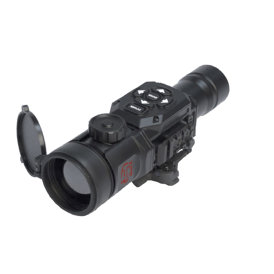
1.2.4. MECHANICAL FUNCTION The mechanical adjustments of the TICO sights allow for physical dif- ferences between individual operators using the system. The scope functions include the Keypad, Output Connector, Eyepiece Diopter Adjustment Ring, Focusing Ring, Battery Module, Accessory Rail, and Weapon Mount. The controls are identified in Figure 1.2. KEYPAD FOCUS KNOB WEAPON... -
Page 19: Electrical Function
ing. The signal processing circuitry translates the infrared detector data into an image that can be viewed on the built-in OLED display. The image is observed through an eyepiece by operator. 1.2.6. ELECTRICAL FUNCTION The electronic circuit is powered by replaceable two 3V lithium bat- teries (CR123A). - Page 20 1-12...
-
Page 21: Chapter 2. Assembly And Preparation
CHAPTER 2 ASSEMBLY AND PREPARATION... -
Page 22: Preparation
2.1. PREPARATION 2.1.1. PREPARATION FOR USE This chapter contains the information necessary to prepare the scope for operation. This includes unpacking, examination for damage, and batteries installation. a. Unpacking The following steps must be accomplished prior to each mission where the sight is used. 1. -
Page 23: Examination For Operation
3. Replace battery cap module of the housing. Screw knob clock- wise until finger tight. Do not over tighten as it will be difficult to remove the next time you replace batteries. BATTERY MODULE FIGURE 2.1. LOADING BATTERY MODULE 2.1.2. EXAMINATION FOR OPERATION Before getting started, make sure to follow these steps: 1. -
Page 24: Assembly
2.2. ASSEMBLY 2.2.1. QUICK RELEASE MOUNT Quick Release Mount (QRM) is used for fast installation/removing the TICO on MIL-STD-1913/Picatinny rail. NOTE Optical axes of the TICO and the riflescope should be matched. Difference of the axes position more than 3 mm is not re-com- mended. -
Page 25: Light Suppressor
3. Turn the lever backwards (parallel) to close the mount. NOTE If using weaver rails, please consult your gunsmith for modi- fication to rail. 2.2.2. LIGHT SUPPRESSOR Your TICO comes with a rubber light suppressor attachment. To use the light suppressor: 1. -
Page 26: Video Output
2.2.3. VIDEO OUTPUT This version of the TICO is equipped with the added feature of being able to connect directly to a remote video monitor or recorder via an integrated video output port. 1. Connect the video cable to the sights video output port. 2. -
Page 27: Chapter 3. Operation
CHAPTER 3 OPERATION... -
Page 28: General Information
3.1. GENERAL INFORMATION 3.1.1. GENERAL This section contains instructions for operation of TICO. The func- tion of controls and indicators is explained. CAUTION The TICO scope is a precision electron-optical instrument and must be handled carefully at all times. 3.1.2. CONTROLS AND INDICATION The TICO is designed to adjust for different users and corrects for most differences. -
Page 29: Operating Procedure
TABLE 3.1. CONTROLS AND INDICATION CONTROLS ITEMS FUNCTIONS AND INDICATORS Controls TICO power. To turn the unit on POWER Button and off press the button ENTER Button Used to select or enter selection Up Arrow Calibration, Reticle Color Down Arrow Brightness, Saved Ballistic Profile Left Arrow Color, Reticle On/Off... -
Page 30: Focusing
NOTE During the warm-up time, a logo comes into view on the mon- ocular display. Next the thermal image replaces the logo. FIGURE 3.2. SWITCHBOARD OF TICO 3.2.2. FOCUSING 1. To focus the scope you need to focus your dayscope first. 2. -
Page 31: Ism - Interactive Symbology Menu
NOTE The front lens should be readjusted for viewing objects at dif- ferent distances. Rotate the focusing ring clockwise for far focus, counterclockwise for near focus. 3.2.3. ISM – INTERACTIVE SYMBOLOGY MENU The TICO features the all new ISM interactive symbology menu that enables you to easily navigate through the features and modes without having to go into a complex menu structure. - Page 32 RETICLE COLOR RETICLE RETICLE ON/ ADJUSTMENT SAVED BALLISTIC PROFILE FIGURE 3.5. ISM RETICLE MENU BATTERY LEVEL FIGURE 3.6. ISM NO MENU INDICATOR...
-
Page 33: Polarity
3.2.4. POLARITY The function of polarity switching is accessible only in Black and White models. WHITE HOT BLACK HOT FIGURE 3.7. DISPLAY POLARITY MODES Polarity: Polarity is the most common used thermal color modes. The function of polarity switching is accessible only in Black and White models. -
Page 34: Brightness
IRONBOW COLOR 1 GLOBOW FIGURE 3.8. COLOR MODES 3.2.5. BRIGHTNESS Brightness allows you to dim or increase the brightness of the dis- play. To cycle through the BRIGHTNESS steps go to ISM Main menu and push the down arrow button for brightness adjustment. Each short push of the buttons will cycle through the BRIGHTNESS modes, correspondingly, in stepwise way. -
Page 35: Manual Image Refresh / Calibration
NOTE Resolution decreases with each step of digital magnification. The reticle has a built in compensation to shift and stay on the target during digital zoom operations as depicted in Figure 3.9. NO ZOOM 2X ZOOM 4X ZOOM RETICLE ON TARGET RETICLE SHIFTS 2X RETICLE SHIFTS 4X FIGURE 3.9. -
Page 36: Reticle Color
DURING CAL CORRECT CAL INCORRECT CAL CORRECT VIEW IF LENS IS COVERED IF LENS IS NOT COVERED FIGURE 3.10. CALIBRATION (NUC) 3.2.8. RETICLE COLOR Your scope has Four reticle colors to choose from: red, green, white, black, the latest firmware also includes many bonus colors. To select reticle colors go to ISM Reticle menu and push Up arrow button to cycle through the reticle colors. -
Page 37: Shut Down Operations
This will bring you to ISM Reticle Adjustment menu which will allow you to do your vertical and horizontal adjustments. To adjust vertical and horizontal adjustments for the scope use cor- responding arrows: • Up Up arrow for up adjustment •... - Page 38 3.2.12. SIGHTING-IN THE CLIP-ON SCOPE 1. Insure your optical day scope is sighted in to your weapon. 2. If possible, lock down the weapon in a shooting vice, this will insure the highest level of accuracy. Now place the day scope reticle on a thermal target at the same distance that the day scope is sighted in to.
- Page 39 5. Adjust the TICO reticule until it is exactly on top of the day scope reticle(still at x1 zoom) (Figure 3.16.). FIGURE 3.16. 6. Exit the reticule adjust mode, and save the day scope reticle position to any ballistic profile location (Figure 3.17.). FIGURE 3.17.
- Page 40 7. Return to the Reticle menu (Figure 3.18.) and scroll through unit the fine line and dot reticle is turned off. Now enter the reticule adjust level. RETICLE COLOR RETICLE TYPE RETICLE POSITION SAVED RETICLE LOCATION FIGURE 3.18. 8. Adjust the TICO image position using the up/down/left/right buttons on the TICO keypad, until the thermal target is centered under the day sight reticle.
-
Page 41: Chapter 4. Maintenance Instructions
CHAPTER 4 MAINTENANCE INSTRUCTIONS... -
Page 42: Preventive Maintenance Checks And Services (Pmcs)
4.1. PREVENTIVE MAINTENANCE CHECKS AND SERVICES (PMCS) 4.1.1. PURPOSE OF PMCS PMCS is performed daily when in use to be sure that the sight is ready at all times. Procedures listed in Table 4.1. are a systematic inspection of TICO that will enable you to discover defects that might cause the sight to fail on a mission. - Page 43 SEQ. ITEM TO CHECKING NOT FULLY MISSION CHECK PROCEDURE CAPABLE IF: Check to ensure: — the focus ring cannot be Focus ring able to moved along the sight body; move along sight Focus Ring — there is free rotation of body.
-
Page 44: Troubleshooting
4.2. TROUBLESHOOTING 4.2.1. GENERAL This section contains information for locating and removal most of the TICO operating troubles which may occur. Each malfunction for an individual component or assembly is followed by a list of tests or inspections that will help determine probable causes and corrective action to take. -
Page 45: Maintenance Procedures
4.3. MAINTENANCE PROCEDURES 4.3.1. SCOPE MAINTENANCE The TICO maintenance consists of external inspection of its com- ponents for serviceability, cleaning and installation of the stan- dard and optional accessories. Maintenance instructions covered elsewhere in this manual (PMCS, troubleshooting, etc.) are not repeated in this section. -
Page 46: Preparing For Extended Storage
4.3.3. PREPARING FOR EXTENDED STORAGE To prepare the TICO for extended storage, perform the following: Check the scope for serviceability as outlined in item 4.1 of this manual. Remove the batteries. Clean the scope and accessories. Replace all items in the case. - Page 48 For customer service and technical support, please contact American Technologies Network Corp. 1341 San Mateo Avenue, South San Francisco, CA 94080 phone: 800-910-2862, 650-989-5100; fax: 650-875-0129 www.atncorp.com ©2014 ATN Corporation...
Need help?
Do you have a question about the TICO series and is the answer not in the manual?
Questions and answers