Table of Contents
Advertisement
Quick Links
Advertisement
Table of Contents

Related Manuals for Automatic Cobra

Summary of Contents for Automatic Cobra
- Page 1 Cobra ® Overhead Garage Door Opener Installation Manual Page 1...
- Page 2 Page 2...
- Page 3 Automatic adjust as necessary. Technology distributor, and must be specially fitted. The Cobra® Overhead Garage Door Opener is suitable for the following types of doors: A - One piece door with horizontal track B - Sectional door with curved track...
-
Page 4: Table Of Contents
Thank you! Welcome to the installation and instruction manual for your new Automatic Technology Cobra overhead garage door opener. Created and designed by the latest technological advances, and using the best possible components in the most stringent manufacturing processes athis opener will provide many years of reliable, faithful and safe service to you and your family. -
Page 5: Product Features
STANDBY (Power Save) MODE If the Cobra® Overhead Garage Door Opener is left for fi ve minutes without any button presses, the unit will enter standby mode. The decimal point indicator on the display will turn on. The unit will continue usual operation. When... -
Page 6: Operating Controls
OPERATING CONTROLS 1. ENGAGE DISENGAGEMENT HANDLE, EASY ACCESS TRANSMITTER The “manual release” engage/disengagement handle has a wireless transmitter within its housing. If the button is pressed it will open, stop or close the garage door. 2 ENGAGE/DISENGAGEMENT CORD When pulled down towards the door this will disengage the door to the manual mode, particularly when there is a power failure. - Page 7 OPERATING CONTROLS 4. DISPLAY General Display Codes dcc ro7 Flashes on the display once the opener powers up (dc opener chain drive, fi rmware revision o7) Reset limits, Door has not been set to its limits Flashes on the display, door is stationary and in Pet Mode Flashes on the display, door is stationary and not at the close, open or pet posi tions Door is currently Open...
- Page 8 OPERATING CONTROLS (continued) 6. TERMINAL P1 (continued) Light (LT) A 24V DC relay of the appropriate contact voltage can be connected to the light terminal (LT) and 24V terminal to control external lights by the transmitter button associated with the cour- tesy light or with any door operation.
-
Page 9: Installation
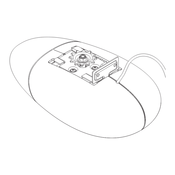
INSTALLATION Tools you may need STEP ONE: PLEASE NOTE - Ensure the bracket is mounted on door at a position of high strength as large forces can be transmitted to the door at this location. Tilt Door Mount Door Bracket fl ush to top of door at centre position (see fi g 1a). Sectional Door Mount Door Bracket about one-third of the way down the top door panel at centre position (see fi... - Page 10 INSTALLATION (continued) STEP TWO: Determine the centre of the door and continue the vertical line through the header as in FIG 2 STEP THREE: Lift the door and fi nd the highest point to which the top of the door reaches. Using an appropriate straight edge and level, transfer the height to the header.
- Page 11 INSTALLATION (continued) STEP SIX: Lay the rail on the ground with channel side facing up. Insert the Traveller and Chain Idler assembly into the end of the rail. Locate chain around the Chain Idler Wheel and through the Traveller as shown (see fi g 5). Ensure chain ends are located at a mid-rail position.
- Page 12 INSTALLATION (continued) STEP EIGHT: Locate chain at Drive unit end onto drive unit sprocket. Keeping chain taut on sprocket, insert drive unit chassis onto rail and slide forward until the chassis upright hits end of rail (see fi gs 7a & 7b). STEP NINE: Install Idler bracket inside door end of rail.
- Page 13 INSTALLATION (continued) STEP ELEVEN: Determine a suitable method to support the drive unit from the ceiling depending of the direction of ceiling batons or joists. Supplied in the box is the Hanger Bracket, (Fig. 9a). The sides of the hanger can be cut along the pre-punched small holes and then folded to the required angle as shown in Fig.
- Page 14 INSTALLATION (continued) STEP THIRTEEN: Place the drive unit on the garage fl oor with corrugated cardboard or old carpet underneath to prevent damage. Lift up the assembled rail and motor unit. Slide the idler bracket over the header bracket tags. Pull the rail back and down so the header bracket tags engage in the slots in the idler bracket as shown in Fig.
- Page 15 INSTALLATION (continued) STEP FIFTEEN: Ensure door is fully closed. Pull traveller and straight arm by hand until straight arm can be attached to Door brack- et (Fig 13a). Use release cord to free Traveller if it engages with chain spool. A curved arm is added to straight arm when the Door bracket is installed below the top of the door.
- Page 16 INSTALLATION (continued) STEP SEVENTEEN: Pull door to half-open position until chain spool engages inside traveller. Plug in power to Drive Unit and switch on. Remove lens by pushing it up from drive unit for programming the opener (Fig 15.). Page 16...
-
Page 17: Door Travel Limits
PROGRAMMING - Door Travel Limits SETTING DOOR TRAVEL LIMITS FIG 16 To code transmitter for setting limits 1. Select Handheld Mode using the LEARN button on the unit. Display shows (H)andheld (Fig. 16) 2. Within 10 seconds, momentarily press the required button on the transmitter. -
Page 18: Safety Force Margin
ADJUSTING SAFETY OBSTRUCTION FORCE NOTE: The Safety Obstruction Force is calculated automatically and set in memory on the Cobra® opener. It is usually not necessary to adjust the Safety Obstruction Force. The only time the force may need to be increased is due to environmental conditions, for example, windy or dusty areas, and areas with extreme temperature changes. -
Page 19: Coding/Deleting Transmitters
CODING TRANSMITTERS PROGRAM A TRANSMITTER BUTTON TO OPERATE THE DOOR 1. Select Handheld Mode using the LEARN button on the unit. FIG 21 Display shows (H)andheld (FIG 21). 2. Within 10 seconds, momentarily press the required button on the transmitter. The decimal point indicator on the display will fl... - Page 20 Coding Hole button on the unit. However, you do need a transmitter that is pre-coded to the Cobra® Overhead Garage Door Opener. 1. Using a small needle press the button through the Coding Hole on a pre-coded transmitter (Fig 25) until the decimal point illuminates and display shows (H)andheld (Fig 26).
-
Page 21: Fiiting Pe Beams
ERASING TRANSMITTERS / FITTING PE BEAMS ERASE TRANSMITTER FROM MEMORY FIG 28 1. Select Erase mode using the LEARN button on the unit. Display shows (E)rase (Fig 28). 2. Press and hold a button on the required transmitter for 2 seconds until the decimal point stays on. -
Page 22: Programming Operating Modes & Courtesy Light
AUTO-CLOSE / COURTESY LIGHT / PET MODE SETTING THE AUTO-CLOSE TIME FIG 32 IMPORTANT NOTICE: IT IS COMPULSORY TO INSTALL A PHOTO ELECTRIC BEAM BEFORE USING THE AUTO CLOSE MODE. 1. Select Auto close mode using the INSTALL button on the unit. Display shows (A)uto close (Fig 32). - Page 23 RESTORE FACTORY SETTINGS / WIRING VACATION LOCK RESTORE FACTORY SETTINGS FIG 37 KEEP ALL TRANSMITTER CODES / RESET ALL OTHER SETTINGS 1. Select Factory Settings mode using the LEARN button on the unit. Display shows (F)actory Settings (Fig 37). 2. Press and hold button 2 on a pre-coded transmitter for 2 seconds until the decimal point stays on, release until the decimal point turns off, then press and hold button 2 again.
- Page 24 WIRING ALARM/STATUS OUTPUT & EXTERNAL LIGHTS WIRING ALARM / STATUS OUTPUT Pressing the transmitter button associated with the Alarm function, FIG 40 the alarm terminal (ALM) will enables the output to pulse for a preset period (500ms) so that an external alarm may be toggled on/off. (Contact the alarm installer for this installation) The ALM terminal shares its function with the Status output.
-
Page 25: Factory Default Settings & Specifications
FACTORY DEFAULT SETTINGS & SPECIFICATIONS Default Step Value Maximum Motor Run Time 30 seconds Courtesy Light Time 3 minutes 10 seconds 10 minutes Obstruction Force Margin Auto Set Auto-Close Time 0 seconds 5 seconds 4 minutes TECHNICAL SPECIFICATIONS INPUT VOLTAGE: 230V -240V ac 50Hz CONTROLLER VOLTAGE: 24V DC MOTOR POWER: 120 Watts MOTOR TYPE: 24V DC Permanent Magnet... - Page 26 Page 26...
-
Page 27: Warranty
Web: www.ata-aust.com.au Email: sales@ata-aust.com.au ©July 2006 Automatic Technology Australia Pty Ltd. All Rights Reserved. SecuraCode® and Cobra® are registered trademarks of Automatic Technology Australia. In an ongoing commitment to product quality ATA reserve the right to change specifi cations without notice. E&OE. - Page 28 AUTOMATIC TECHNOLOGY AUSTRALIA PTY LTD ABN 11 007 125 368 6-8 Fiveways Boulevard, Keysborough, Victoria, 2173 Tel: +61 3 9532 2788 Fax: +61 3 9532 2799 Web: www.ata-aust.com.au Email: sales@ata-aust.com.au Page 28...
Need help?
Do you have a question about the Cobra and is the answer not in the manual?
Questions and answers