
Related Manuals for Signet INTEGRITY

Summary of Contents for Signet INTEGRITY
- Page 1 INTEGRITY VOICE ALARM ROUTING MATRIX Installation and Maintenance Manual Approved Document No. DCS0003214 Rev 0 (8/2/05)
-
Page 2: Table Of Contents
A basic Integrity system with six zones ........ -
Page 3: Important Notes
EU Council Directives. This product has been manufac- tured in conformance with the requirements of all applicable EU Council Directives. Integrity Voice Alarm Routing Matrix Installation & Maintenance Manual • Approved Doc. No. DCS0003214 Rev 0 (8/2/05) • Page 3... -
Page 4: Basic Overview And Key Features
Integrity schematic template 8 audio channels Audio Inputs Audio Outputs Integrity Voice Alarm Routing Matrix Installation & Maintenance Manual • Approved Doc. No. DCS0003214 Rev 0 (8/2/05) • Page 4... -
Page 5: A Basic Integrity System With Six Zones
8 audio channels Emergency Microphone To amplifiers Evacuate Message and loudspeakers Alert Message Fire Alarm C1-6 Interface Audio Inputs Audio Outputs Integrity Voice Alarm Routing Matrix Installation & Maintenance Manual • Approved Doc. No. DCS0003214 Rev 0 (8/2/05) • Page 5... -
Page 6: A 16 Zone System With Four Paging Consoles
Microphone Evacuate Message Alert Message Zonal paging microphone Local paging microphone Music source Fire Alarm Interface Audio Inputs Audio Outputs Integrity Voice Alarm Routing Matrix Installation & Maintenance Manual • Approved Doc. No. DCS0003214 Rev 0 (8/2/05) • Page 6... -
Page 7: A 64 Zone System With Separate Message Stores
Zonal Emergency Microphone Fire Alarm Fire Alarm CI-16 Interface CI-16 Interface Fire Alarm Fire Alarm CI-16 Interface CI-16 Interface Integrity Voice Alarm Routing Matrix Installation & Maintenance Manual • Approved Doc. No. DCS0003214 Rev 0 (8/2/05) • Page 7... -
Page 8: A 58 Zone System With Synchronized Messages
Zonal Emergency Microphone Fire Alarm Fire Alarm CI-16 Interface CI-16 Interface Fire Alarm Fire Alarm CI-16 Interface CI-16 Interface Integrity Voice Alarm Routing Matrix Installation & Maintenance Manual • Approved Doc. No. DCS0003214 Rev 0 (8/2/05) • Page 8... -
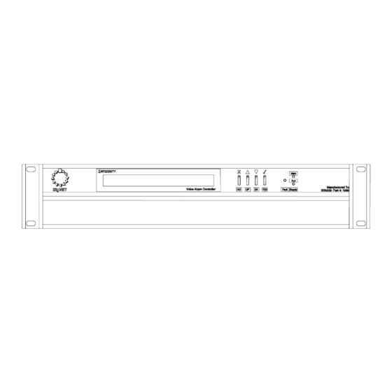
Page 9: The Integrity Mainframe
Now tighten all four screws a bit at a time, taking care not to overtighten and strip the thread in the rails. Integrity Voice Alarm Routing Matrix Installation & Maintenance Manual • Approved Doc. No. DCS0003214 Rev 0 (8/2/05) • Page 9... -
Page 10: Display And Controls
• In an operational system it can be connected to a PC to provide status and fault informa- tion to a terminal program such as HyperTerminal, from which the data may be printed. Integrity Voice Alarm Routing Matrix Installation & Maintenance Manual • Approved Doc. No. DCS0003214 Rev 0 (8/2/05) • Page 10... -
Page 11: Internal Layout
CH9-CH16 slots These slots take any of the currently supported audio output cards or control cards. Integrity Voice Alarm Routing Matrix Installation & Maintenance Manual • Approved Doc. No. DCS0003214 Rev 0 (8/2/05) • Page 11... -
Page 12: Integrity Components
This card is used to connect unbalanced stereo and to select it for routing. It has a pair of female phono (RCA) connectors, a four gang DIP switch and a six-way ‘Weidmüller’ connector. Integrity Voice Alarm Routing Matrix Installation & Maintenance Manual • Approved Doc. No. DCS0003214 Rev 0 (8/2/05) • Page 12... -
Page 13: Op2 Two Zone Audio Output Card
7 and 8 may be used instead. Mainframe 9-pin male 9-pin female Integrity Voice Alarm Routing Matrix Installation & Maintenance Manual • Approved Doc. No. DCS0003214 Rev 0 (8/2/05) • Page 13... -
Page 14: Integrity Mainframe Menu Structure
If the fault is not present, it will reset the fault counter to zero and the fault will not dis- play. Integrity Voice Alarm Routing Matrix Installation & Maintenance Manual • Approved Doc. No. DCS0003214 Rev 0 (8/2/05) • Page 14... -
Page 15: Configuration - The Integrity Editor
This page is used to select the priorities each audio input has over other inputs, to associ- ate input controls with them and to select in which output zones they will play. Integrity Voice Alarm Routing Matrix Installation & Maintenance Manual • Approved Doc. No. DCS0003214 Rev 0 (8/2/05) • Page 15... -
Page 16: Configuring The Hardware
Integrity Voice Alarm Routing Matrix Installation & Maintenance Manual • Approved Doc. No. DCS0003214 Rev 0 (8/2/05) • Page 16... - Page 17 Other functions that can be changed here are output levels for different types of input and operation of the open collector output. Integrity Voice Alarm Routing Matrix Installation & Maintenance Manual • Approved Doc. No. DCS0003214 Rev 0 (8/2/05) • Page 17...
- Page 18 Input Image to something more suitable, such as a green microphone for a non-life safety microphone, or a CD for a CD player. Integrity Voice Alarm Routing Matrix Installation & Maintenance Manual • Approved Doc. No. DCS0003214 Rev 0 (8/2/05) • Page 18...
- Page 19 Note that this is a simulation – the correct messages must be installed into the SoundVault card using the separate SVM upload/ download program. Integrity Voice Alarm Routing Matrix Installation & Maintenance Manual • Approved Doc. No. DCS0003214 Rev 0 (8/2/05) • Page 19...
- Page 20 The usual type is the MPC Series, which is a range of panels with between 16 and 64 programmable buttons. Integrity Voice Alarm Routing Matrix Installation & Maintenance Manual • Approved Doc. No. DCS0003214 Rev 0 (8/2/05) • Page 20...
- Page 21 The two red circles on the left show the progress of the upload, which takes place in the following sequence: Integrity Voice Alarm Routing Matrix Installation & Maintenance Manual • Approved Doc. No. DCS0003214 Rev 0 (8/2/05) • Page 21...
- Page 22 Message 2, 22 s Message 4, 11 s Message 1, 33 s Message 1, 11 s Message 3, 33 s Integrity Voice Alarm Routing Matrix Installation & Maintenance Manual • Approved Doc. No. DCS0003214 Rev 0 (8/2/05) • Page 22...
- Page 23 There are eight audio input cards and, when each of these is plugged in to a slot, it connects to one of the audio buses. Integrity Voice Alarm Routing Matrix Installation & Maintenance Manual • Approved Doc. No. DCS0003214 Rev 0 (8/2/05) • Page 23...
-
Page 24: Fault Logging
PCs power may be removed or files deleted in error. Select a suitable name and icon, and click OK. We suggest ‘Integrity Logging’. Integrity Voice Alarm Routing Matrix Installation & Maintenance Manual • Approved Doc. No. DCS0003214 Rev 0 (8/2/05) • Page 24... - Page 25 Having set up the connection, it is normal to save the log directly to file. To do this, select ‘Capture Text’ from the Transfer menu. You will be asked for a file name to save it to. Integrity Voice Alarm Routing Matrix Installation & Maintenance Manual • Approved Doc. No. DCS0003214 Rev 0 (8/2/05) • Page 25...
- Page 26 To print later just open the log you created under item 6 in a suitable editor package such as Notepad, and select ‘Print’ from the file menu. Integrity Voice Alarm Routing Matrix Installation & Maintenance Manual • Approved Doc. No. DCS0003214 Rev 0 (8/2/05) • Page 26...
-
Page 27: Dimensions, Power Requirements & Current Consumption
Fully populated with smallest paging console (16 zone) fitted and all LEDs lit = 350mA Current draw of each input or output card = 16 to 20mA Integrity Voice Alarm Routing Matrix Installation & Maintenance Manual • Approved Doc. No. DCS0003214 Rev 0 (8/2/05) • Page 27...
Need help?
Do you have a question about the INTEGRITY and is the answer not in the manual?
Questions and answers