Table of Contents
Advertisement
Advertisement
Table of Contents

Summary of Contents for Van Norman 204
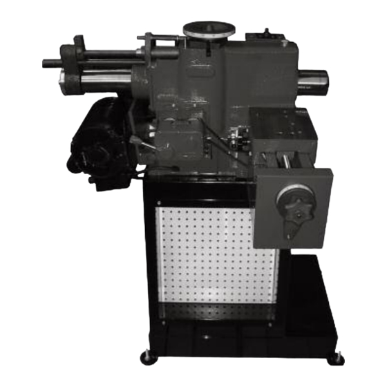
- Page 1 Heavy Duty Combination Brake Lathe Instruction Manual and Parts List Van Norman 500 57 St., Marion, IA 52302 888-855-1789 319-377-9101 (FAX) Copyright 2005 All Rights Reserved. Equipment specifications, options and accessories subject to change without notice.
- Page 3 (wheel dresser/diamonds/abrasives) consumed in normal operation of the machine. Van Norman disclaims all other warranties, expressed or implied, as to the quality of any goods, including implied warranties of MERCHANTABILITY and FITNESS FOR PARTICULAR PURPOSES. UNDER NO CIRCUMSTANCES WHATSOEVER, SHALL Van...
- Page 5 If evidence of damage exists, contact the shipper and Van Norman immediately. Although Van Norman is not responsible for damage incurred during transit, you will be provided assistance in preparation and filing of any necessary claims.
- Page 6 The specifications put forth in this manual were in effect at the time of publication. However, owing to Van Norman’s policy of continuous improvement, changes to these specifications may be made at any time without obligation.
-
Page 7: Safety Instructions
Van Norman/Kwik-Way recommends the use of anti-skid floor strips on the floor area where the operator normally stands and that each machine's work area be marked off. -
Page 8: Specifications
Machine Net Weight…………….. 643 lbs. (292 kg) Domestic Shipping Weight……… 730 lbs. (331 kg) Export Shipping Weight………… 835 lbs. (379 kg) Van Norman is committed to product innovation and improvement and therefore reserves the right to change product specifications without notice. Van Norman... - Page 9 Any Overload or Undervoltage protection devices are not furnished as standard equipment and may be purchased locally or by Special Quote from Van Norman. The main spindle is to revolve CLOCKWISE when facing the work light.
- Page 10 204 Heavy Duty Combination Brake Lathe INSTALLATION (continued) 4. Grease Spindle Bearing (Figure 3) once a month using a lithium based grease with moly. The grease should be an NLGI Grade 1, GC-LB. Figure 3 Cleaning / Maintenance 1. Do not use an air hose to clean machine. Use a brush to clear chips away. Clean daily after use.
- Page 11 204 Heavy Duty Combination Brake Lathe COMPONENT/CONTROL IDENTIFICATION AND FUNCTION 1. Spindle Stop 2. Handwheel for Spindle Position 3. Oil Fill (Oil Daily #30) 4. On/Off/Light Switch 5. Oil Fill & Breather 6. Spindle Arbor 7. Tool Bar (for Drum Turning) – 204S 8.
- Page 12 204 Heavy Duty Combination Brake Lathe STANDARD & OPTIONAL EQUIPMENT STANDARD MACHINES 204C Disc/Drum Lathe with Powered & Manual Cross-Feed Slides, Base and Standard Equipment Part No. Description 804-2474-01 115V, 60 Hz, 1 Ph 804-2474-05 230V, 60 Hz, 1 Ph...
- Page 13 204 Heavy Duty Combination Brake Lathe STANDARD & OPTIONAL EQUIPMENT (continued) Miscellaneous Part No. Description 804-2059-20 Chip Tray 108-1061-00 Vented Silencer-Rotor 109-1032-09 Spacer, 1 x 1.5 x 1.5 804-8665-41 Solid Rotor Silencer, Magnetic Band, .250" x 48" (6.35 x 1219.2 mm)
- Page 14 204 Heavy Duty Combination Brake Lathe STANDARD & OPTIONAL EQUIPMENT (continued) Optional Accessories Part No. Description 804-8626-13 Hubless Adapter Set, Large Size for 1" Arbor, Bore Range 4.00"–5.75" (101.6-146.05 mm) 804-2020-23 Rotor Locator 804-4161-85 Cone, 3.68" x 5.93" (93.47 x 150.62mm)
- Page 15 204 Heavy Duty Combination Brake Lathe STANDARD & OPTIONAL EQUIPMENT (continued) Optional Accessories 804-8664-66 Medium Truck Set, for 2" Arbor, Bore Range 2.15"–6.10" (54.61–154.94mm) for Hubless Drums /Discs 804-8664-53 Cone, 2.15"–2.80" (54.6–71.1mm) 804-8664-54 Cone, 2.70"–3.35" (68.5–85.0mm) 804-8664-55 Cone, 3.25"–3.90" (82.5–99.0mm) 804-8664-56 Cone, 3.80"–4.45"...
- Page 16 A larger diameter drum or rotor requires a lower RPM. For most applications, Van Norman recommends the middle pulley groove for passenger cars and light truck brake drums and rotors. The outer pulley groove is for extremely small rotors and drums and the inner pulley groove for very large drums and rotors.
- Page 17 204 Heavy Duty Combination Brake Lathe OPERATION (continued) CHATTER CONTROL 1. Brake drums are dish or bell shaped and have a tendency to chatter. This can result in a wavy or chatter finish accompanied by excessive noise. THE VIBRATION DAMPENER BELT MUST BE USED AT ALL TIMES to prevent chatter. Securely wrap belt around the outside of the drum or use proper “O”...
- Page 18 204 Heavy Duty Combination Brake Lathe OPERATION (continued) RECONDITIONING DRUMS 1. The knob (Figure 8B) should be loosened when turning drums to insure spindle will move out during operation. This screw must be tightened when cutting rotors. 2. This knob (Figure 9) should be tightened when doing drums and slide is in position.
- Page 19 204 Heavy Duty Combination Brake Lathe OPERATION (continued) 5. To disengage feed loosen wing nut (Figure 12A) and slide stop (Figure 12B) to desired position. 6. Reset stop (Figure 12B) every time machine is used on a different width drum. If properly set, the machine will disengage automatically when it reaches the stop.
- Page 20 204 Heavy Duty Combination Brake Lathe OPERATION (continued) 10. Wrap and secure the drum silencer band tightly around the drum (Figure 14). 11. Turn the cross feed handwheel and the spindle feed handwheel to their maximum clockwise position. Then back off the cross feed handwheel 2 turns and the spindle feed handwheel 4 turns.
- Page 21 204 Heavy Duty Combination Brake Lathe OPERATION (continued) TURNING DISC BRAKES 1. Tighten thumb screw (Figure 8 B Page 13) 2. Loosen knob (Figure 9 Page 14) 3. Each brake disc should be carefully inspected for scoring, rust, ridges (at the inner and outer circumference of the rotor) and hard spots.
- Page 22 204 Heavy Duty Combination Brake Lathe OPERATION (continued) 6. Feed in the slide assembly with crank [Figure 18 A). (Figure 18 B) Locking nut is turned in to engage slide power. (Must be loose to turn slide in or out manually.
- Page 23 204 Heavy Duty Combination Brake Lathe MAINTENANCE (continued) DISASSEMBLY, REPAIR, REPLACEMENT AND REASSEMBLY 1. Unplug machine. 2. Remove tooling from machine. 3. Remove arbor by loosening draw bar. 4. Drain oil. 5. You are now ready to start repair. SPINDLE BEARING NOTE: It is rare for the spindle bearing to need replacement.
- Page 24 204 Heavy Duty Combination Brake Lathe BASIC MACHINE Item Part No. Description 804-2043-00 Body 804-1184-28 Breather 804-3020-06 Bearing (Prior to 1984)( Not Shown) 804-1415-69 Front Bearing Oil Seal 804-3040-65 Work Light Window 804-1050-21 Screw (10-32 x 3/8) 000-1154-60 Washer (#10)
- Page 25 204 Heavy Duty Combination Brake Lathe BASIC MACHINE Van Norman 888-855-1789...
- Page 26 204 Heavy Duty Combination Brake Lathe VERTICAL SHAFT ASSEMBLY Item Part No. Description Qty. 804-2043-00 Body 804-1094-24 Groove Pin 804-2040-19 Upper Collar 804-1062-54 Oiler 000-4400-10 Handwheel Handle 804-2040-75 Vertical Shaft Handwheel 804-2040-18 Handwheel Spring 804-2040-76 Gear 804-2040-19 Lower Collar 804-1094-24...
- Page 27 204 Heavy Duty Combination Brake Lathe VERTICAL SHAFT ASSEMBLY Van Norman 888-855-1789...
- Page 28 204 Heavy Duty Combination Brake Lathe SPINDLE CLAMP ASSEMBLY Item Part No. Description Qty. 804-2040-26 Push Rod 804-8035-81 Retaining Ring 804-1243-55 Compression Spring 000-1155-33 Washer, 3/8 Flat 804-2040-63 Sleeve 000-1180-28 Lockwasher, (5/16) 000-0167-64 SHCS (5/16-18 x 1/2) 804-1247-55 Retaining Ring (5000-112)
- Page 29 204 Heavy Duty Combination Brake Lathe SPINDLE CLAMP ASSEMBLY Van Norman 888-855-1789...
- Page 30 204 Heavy Duty Combination Brake Lathe RIGHT REAR OF MACHINE Item Part No. Description Qty. Bulk Cable, 36”' 800-8014-71 Strain Relief 000-1261-01 110V Motor Cable 000-1160-17 Washer, (5/16) 000-1180-28 Lockwasher (5/16) 000-0102-86 HHCS (5/16-18 x 3/4) 804-1405-24 Motor 804-8682-62 Pulley...
- Page 31 204 Heavy Duty Combination Brake Lathe RIGHT REAR OF MACHINE Van Norman 888-855-1789...
- Page 32 204 Heavy Duty Combination Brake Lathe 804-8690-56 DISC ASSEMBLY Item Part No. Description Qty. 804-8693-77 Hand Lock Down 804-1407-54 Washer, .312 Flat 804-1258-12 Dowel Pin (.75 x 2) 804-1405-35 Spring 804-8678-54 R.H. Tool Holder 804-8678-55 L.H. Tool Holder 804-8690-23 Base Plate...
- Page 33 204 Heavy Duty Combination Brake Lathe 804-8690-56 DISC ASSEMBLY Van Norman 888-855-1789...
- Page 34 204 Heavy Duty Combination Brake Lathe POWER FEED ATTACHMENT FOR FACING DISC BRAKES Item Part No. Description Qty. 804-2041-42 000-0491-23 SSS (3/8-16 x 1 3/4) 804-1405-31 Knob 804-1116-33 Brass Plug 000-0170-35 SHCS (3/8-16 x 1 1/2) 804-2041-18 Power Facing Feed Slide...
- Page 35 204 Heavy Duty Combination Brake Lathe POWER FEED ATTACHMENT FOR FACING DISC BRAKES Van Norman 888-855-1789...
- Page 36 204 Heavy Duty Combination Brake Lathe ELECTRICAL EQUIPMENT Item Part No. Description Qty. 804-2043-00 Body 804-1413-57 Electrical Cover 800-8014-69 Strain Relief 804-1415-26 Wire Clip 804-1050-21 Screw (10-32 x 3/8) 804-1413-56 Switch 804-8657-78 Electrical Box 804-1050-21 Screw (10-32 x 3/8) 804-8109-79...
- Page 37 204 Heavy Duty Combination Brake Lathe ELECTRICAL EQUIPMENT Van Norman 888-855-1789...
- Page 38 204 Heavy Duty Combination Brake Lathe Van Norman 888-855-1789...
- Page 39 204 Heavy Duty Combination Brake Lathe Van Norman 888-855-1789...
- Page 40 204 Heavy Duty Combination Brake Lathe Van Norman 888-855-1789...
- Page 41 204 Heavy Duty Combination Brake Lathe Van Norman 888-855-1789...
- Page 43 Van Norman A Division of Kwik-Way Products Inc. 500 57 St., Marion, IA 52302 USA 888-855-1789 or 319/377-9421 319/377-9101 (FAX) www.van-norman.com service@kwik-way.com...
Need help?
Do you have a question about the 204 and is the answer not in the manual?
Questions and answers