
Related Manuals for Cleaver-Brooks CFV


Summary of Contents for Cleaver-Brooks CFV
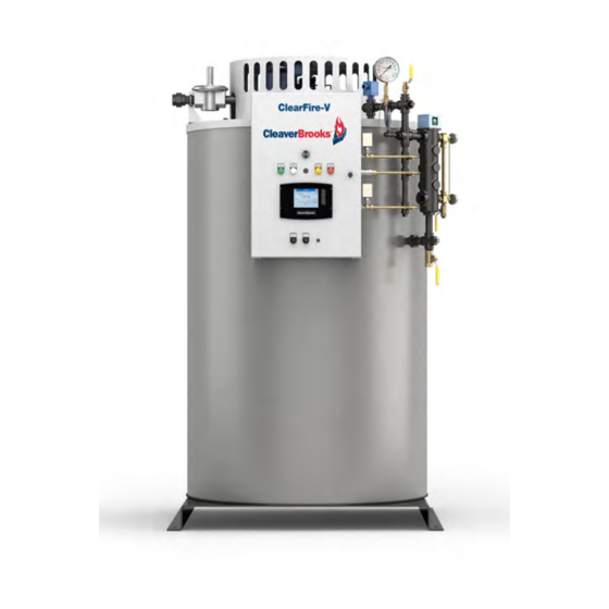
- Page 1 ® ClearFire Model CFV Vertical Steam Boiler Startup Guide 750-288 www.cleaverbrooks.com...
- Page 2 The boiler and its gas connection must be leak tested before placing the boiler in operation. Notice Refer to CFV Operation and Maintenance Manual - CB Part Number 750-269 Where required by the authority having jurisdic- tion, the installation must conform to the Standard for Controls and Safety Devices for Automatically Fired Boilers, ANSI/ASME CSD-1.
-
Page 3: Before Start-Up
CFV Startup Guide 1 - BEFORE STARTUP Your Cleaver-Brooks boiler has been factory fire-tested and the control system pre-configured for a trouble- free startup. To help ensure a successful lightoff and reliable operation, certain initial conditions should be observed. Do not attempt to place the boiler into service without verifying that all connections - fuel, steam and water piping, electrical connections, stack, and combustion air provisions - have been installed properly and in accordance with any applicable codes or regulations. -
Page 4: Gas Piping
A manually operated shut-off valve and pressure regulator are provided at the CFV gas valve, use the as standard on the Model CFV boiler. It is recommended to install an test port on the valve inlet flange (see below). Do not approved gas filter or strainer in the gas supply line to the boiler. -
Page 5: Boiler Water-Side Connections
1.5 Electrical Connections Refer to Figure 3 for CFV wiring and cable connections. See also wiring diagram on page 13. A qualified electrician or service technician must make the electrical connections to the boiler; all local electrical and building codes should be adhered to. - Page 6 CFV Startup Guide 1.6 Safety Controls Users should take note of the safety controls installed as standard on the Model CFV. Minor adjustments to the initial factory settings of some controls may be necessary for your particular installation. It is required to test all controls for proper functioning prior to starting the boiler for the first time. Step- by-step procedures for testing the controls can be found in the CFV manual (Chapter 4 - Commissioning).
-
Page 7: Filling Boiler
CFV Startup Guide Control panel interior CB FALCON CONTROLLER ALWCO CONTROLLER LWCO CONTROLLER / PUMP CONTROL Figure 5 Water level controls Limit Controls (see Figure 6) The operating and high pressure limit controls are externally mounted to the control trim piping. For control settings and testing instructions, see the boiler operation manual. -
Page 8: Starting The Boiler
The use of soft water is highly recommended. Failure to observe this recommendation can lead to dangerous operating conditions, and may result in damage to the boiler. If necessary, your Cleaver-Brooks representative can provide additional information regarding your water softening requirements. -
Page 9: Controller Configuration
The CB Falcon controller is factory pre-configured with default parameter upper left of the display screen always returns to the settings for the Model CFV. Prior to starting the boiler, verify that the Home Page. factory default settings are correct for your application. See the boiler operation manual (Chapter 4 - Commissioning) for the parameter list and parameter change procedure. -
Page 10: Manual Operation
CFV Startup Guide BURNER SWITCH button Figure 11 Operation screen Turn the <Burner switch> screen button to ON. The burner is now Burner Sequence: enabled. STANDBY (burner switch off or no demand) Turn the control panel DEMAND switch to LOC (local). The burner sequence should now begin. - Page 11 Operating outside of acceptable limits could result in light off and flame failure problems. • Verify gas pressure remains within limits shown in Table 1. • A new boiler should be cleaned by boil-out prior to being placed into service. See Chapter 4 of the CFV manual for boil-out procedure.
-
Page 12: Lockouts, Holds, And Alerts
CFV Startup Guide 5 - LOCKOUTS, HOLDS, AND ALERTS To assist in monitoring boiler operation, the CB Falcon control system employs messages of three types: Lockouts, Holds, and Alerts. • Lockouts and Holds indicate interruptions in boiler operation, whether occurring as part of the normal operating sequence or due to an abnormal condition. - Page 13 CFV Startup Guide Figure 15 CFV Wiring Diagram 115V/1PH AC FUSED BLOWER MOTOR FUSE SELECTION POWER SUPPLY W/ IGNITION CFV HP BLOWER MODEL RATING, CLASS CC GROUNDED NEUTRAL 10 - 30 G1G170-AB05-20 TRANSFORMER G3G200-GN26-01 12 A 50 - 60 G3G250-GN39-01...
- Page 14 CFV Startup Guide Part No. 750-288...
- Page 15 CFV Startup Guide Part No. 750-288...
- Page 16 e-mail: info@cleaverbrooks.com Web Address: http://www.cleaverbrooks.com...
Need help?
Do you have a question about the CFV and is the answer not in the manual?
Questions and answers