Table of Contents
Advertisement
Issue 1.0 July 2014
Vision 2.3 Twin Duct
Air Conditioner/Heat Pump
Optional Low Pressure Hot Water Fan Coil Model Available
w w w . p o w r m a t i c . c o . u k
Installation, Servicing, and Users
Instructions
Vision2.3
GB & IE
H E A T I N G
/ /
V E N T I L A T I O N
/ /
A I R C O N D I T I O N I N G
Advertisement
Table of Contents

Related Manuals for Powrmatic Vision 2.3 Twin Duct

Summary of Contents for Powrmatic Vision 2.3 Twin Duct
- Page 1 Issue 1.0 July 2014 Vision 2.3 Twin Duct Air Conditioner/Heat Pump Optional Low Pressure Hot Water Fan Coil Model Available w w w . p o w r m a t i c . c o . u k Installation, Servicing, and Users Instructions Vision2.3...
- Page 2 Powrmatic ‘General Conditions of Sales’ have been observed. Except for the obligation of Powrmatic Ltd to perform warranty repairs during the guarantee period Powrmatic will not be liable in respect of any claim for direct or indirect consequential losses, including loss of profit or increased cost arising from loss of use of the air conditioner, or any event arising there from.
-
Page 3: Safety Pictograms
Dear Customer - thank you for choosing Powrmatic. We appreciate you buying one of our high quality products and know that you have made the best choice. We pride ourselves by manufacturing products that provide clean, comfortable and safe working environments worldwide together with the personal & professional service and back-up you deserve. -
Page 4: Table Of Contents
Users, Installation, Servicing and User Instructions CONTENTS Title Section Contents Page General General warning Fundamental safety rules Description Receipt and unpacking Storage Handling Shipping dimensions and weight Supplied components Unit parts Installation Installation mode Choosing the position of the unit Assembling the unit Assembling air ducts and external shutters 12 Mounting the appliance on the bracket... -
Page 5: General Warning
1.1 General Warning (UIS) After unpacking, check that the contents are If the temperature is set too low or too high, not intact and that all parts are included. If they are only will it be unhealthy, but it is also a waste of not, please contact the supplier who sold you the energy. -
Page 6: Description
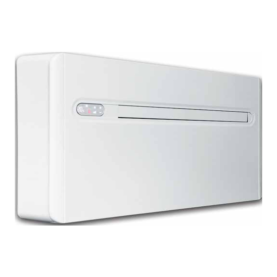
1.3 Description (UIS) The Vision 2.3 is the new solution by Powrmatic, a signifi- easier to find drilling tools, with lower aesthetic impact. cant step towards reducing the aesthetic impact of air conditioners. Being only 16 centimetres deep, the Vision Easy to install 2.3 is the thinnest and less bulky in this category, there-... -
Page 7: Shipping Dimensions And Weight
1.7 Shipping dimensions and weight (UIS) Packing “Vision 2.3” 10 HP Dimensions Weight Length 1110 Height Depth 1.8 Supplied components (UIS) The air conditioner supplied comprises of the parts listed in the following table. Before assembly, please check that they are all included. External grids for air inlet and outlet with springs CR2025 3V remote control battery and chains (2 pcs) -
Page 8: Unit Parts
1.9 Unit parts (UIS) Air outlet flaps Air filters Touch-screen display Outdoor air outlet fan Front panel Outdoor air heat exchanger Outdoor air suction Compressor Outdoor air outlet Indoor air heat exchanger Air suction grid Electronic board Page 8 Vision 2.3 Air Conditioner Range Issue 1.0 June 2014... -
Page 9: Installation Mode
2.1Installation mode (I) Before installing the conditioner, it is essential to calculate Cover large windows exposed to sunlight with curtains or the summer thermal loads (and winter ones for the with external masking (blinds, porches, reflecting films models with a heat pump) of the room. The more accu- etc.) rate calculations, the better the product will work. -
Page 10: Assembling The Unit
2.3 Assembling the unit (I) The maximum length of the holes is of 1 m and The holes must be drilled slightly downward there must be no bends. Use the supplied grids towards the outside, to avoid water from entering or grids with the same characteristics. - Page 11 Condensation drain predisposition The exact position in which to place the pipe mouth is indicated on the template. For heat pump appliances, a condensation drain pipe Check that the expelled water does not cause (Ø10mm, internal, not supplied) must be connected to the any damage, or problem to people or objects.
-
Page 12: Assembling Air Ducts And External Shutters
2.4 Assembling air ducts and external shutters (I) Once the holes have been made, place the supplied Fix the chains to the internal flange’s hooks plastic sheet inside them. Use a bolt cutter to remove any excess chain. Roll up the sheet and insert it in the hole, checking that Anchor the hook of the chain to wall “B”. -
Page 13: Mounting The Appliance On The Bracket
2.5 Mounting the appliance on the bracket (I) After checking that the bracket is anchored to the wall and on the back of the appliance especially where the air that all necessary electrical connections and condensa- ducts are connected. tion drain have been made, you can mount the condition- er. -
Page 14: High/Low Installation Configuration
CP presence contact input connec- It is essential to disconnect the main switch before making any connection or maintenance operation in order to tion avoid any risk of electrocution. To carry out direct connections and substitute the power When the CP contact opens (connected to a free non-live cord using the cable in the wall, proceed as follows: contact) the appliance is put in standby and CP appears Space the appliance from the wall using wooden... - Page 15 After adjusting the air outlet flap position, it is necessary to If no other operations are performed in the set up the electronic control of the appliance: following 2 seconds, the new setting is memo- Press and hold the button on the display for rised.
-
Page 16: Setting Cool Only Or Heat Only Modes
2.8 Setting cool only or heat only modes (I) It is possible to deactivate the heating or the cooling Press the “A” key for Ho (heating only) mode. modes following a simple procedure. Wait for 3 seconds without touching anything to memorise Pres and hold the “A”... -
Page 17: Periodic Maintenance
3.1Periodic Maintenance (S) The air conditioner you have bought has been designed Clean the air filter after a period of continuous to keep maintenance operations to a minimum, which use and in accordance with the concentration of only concern the following cleaning operations. impurities in the air, or when you wish to start-up the appliance after a period of inactivity. -
Page 18: Troubleshooting
3.2 Troubleshooting (S) In case of a malfunction, please refer to the following lem is not solved, please contact the authorised technical table. If, after performing the suggested checks, the prob- assistance. Anomaly Possible cause Solution The appliance No power supply Check you have a power supply to the unit (try turning on a does not switch light switch, or plugging in another electrical device.) -
Page 19: Technical Data
3.3 Technical data (S) Please read the data plates to obtain the technical data listed below. Power supply voltage Maximum absorbed power Maximum absorbed current Amount of refrigerant gas Casing protection level Max. Working pressure Technical data U.M. Vision 2.3 10HP Cooling power (1) 2.30 Heating power (2) -
Page 20: Management Of The Appliance With The Touch-Screen Display
4.1 Management of the appliance with the touch-screen displayd (u) Normally, the display shows the operating status (see In addition, it is possible to select the various functions by Description of machine functioning paragraph) as well as pressing the symbols. any alarms (see Display alarms paragraph). -
Page 21: Description Of Machine Functioning
4.3 Description of machine functioning (U) General start-up and management Once such operations have been performed, it is possible to manage the system using the symbols on the In order to manage the appliance using the remote control touch-screen or the remote control in order to transmit and the touch-screen, the main switch on the electrical commands to the internal unit, the top part of the remote power supply lime must be turned on (its exact position... -
Page 22: Control Of Air Flow Direction
Key/Display Operation Ventilation only mode By selecting this mode, the compressor is not activated and the appliance does not intervene on room temperature or humidity. It is possible to choose the fan speed. Heating only mode In this mode, the appliance heats the room. Set on heating only mode, the appliance defrosts the evaporative battery periodically if necessary. -
Page 23: Advice For Energy Saving
Key/Display Operation Timer mode setting The appliance o ers users the chance to programme its activation and deacti- vation according to their needs. While the conditioner is on, it is possible to programme the switch-o time by pressing the timer button and setting the number of hours (1 to 24) after which the appliance will be put in stand-by. - Page 24 HEATING DIVISION Hort Bridge Ilminster, Somerset TA19 9PS Tel: 01460 53535 Fax: 01460 52341 Every effort is made to ensure accuracy at time of going to press. However as part of our policy of continued product improvement, we reserve the right to alter specification without prior notice. Page 24 Vision 2.3 Air Conditioner Range Issue 1.0 June 2014...
Need help?
Do you have a question about the Vision 2.3 Twin Duct and is the answer not in the manual?
Questions and answers