
Related Manuals for Blade Network Technologies RackSwitch G8124


Summary of Contents for Blade Network Technologies RackSwitch G8124
-
Page 1: Installation Guide
™ RackSwitch G8124 Installation Guide Part Number: BPP-00018-01, December 2009 2350 Mission College Blvd. Suite 600 Santa Clara, CA 95054 www.bladenetwork.net... - Page 2 FAR 12.211- 12.212 (Oct. 1995), DFARS 227.7202 (JUN 1995) and DFARS 252.227-7015 (Nov. 1995). BLADE Network Technologies, Inc. reserves the right to change any products described herein at any time, and without notice. BLADE Network Technologies, Inc. assumes no responsibility or liability arising from the use of products described herein, except as expressly agreed to in writing by BLADE Network Technologies, Inc.
-
Page 3: Table Of Contents
Required Tools Package Contents Environmental Requirements Preventing Electric Shock Preventing Electrostatic Discharge Installing the RackSwitch G8124 in a Standard Equipment Rack Installing the RackSwitch G8124 in an iDataPlex Rack Installing the RackSwitch G8124 in a 4-post Rack BPP-00018-01, December 2009... - Page 4 RackSwitch G8124 Installation Guide Initializing the RackSwitch G8124 Default Configuration Configuring an IP Interface Using the Boot Management Menu Installing an SFP or SFP+ Transceiver SFP+ Optical Transceiver SFP Copper Transceiver Troubleshooting System LEDs Do Not Light Port link LED Does Not Light...
-
Page 5: Preface
This Installation Guide is intended for network installers and system administrators engaged in configuring and maintaining a network. It assumes that you are familiar with your RackSwitch G8124, your Web browser, Ethernet concepts, IP addressing, the IEEE 802.1D Spanning Tree Protocol, and SNMP configuration parameters. -
Page 6: How To Get Help
RackSwitch G8124 Installation Guide How to Get Help If you need help, service, or technical assistance, call Blade Network Technologies Technical Support: US toll free calls: 1-800-414-5268 International calls: 1-408-834-7871 You also can visit our web site at the following address: http://www.bladenetwork.net... -
Page 7: Chapter 1: Rackswitch G8124 Description And Specifications
RackSwitch G8124 Description and Specifications The RackSwitch G8124 is an all 10Gb Ethernet rackable aggregation switch with unmatched line-rate Layer 2 performance. The G8124 uses a wire-speed, non-blocking switching fabric that provides simultaneous wire-speed transport of multiple packets at low latency on all ports. -
Page 8: Software Features
IP forwarding IGMP Snooping v1, v2, v3 4K ARP entries RIP v1, v2 OSPF Quality of Service 802.1p priority queues Differentiated Services Code Point (DSCP) support Availability Layer 2 Failover VRRP Chapter 1: RackSwitch G8124 Description and Specifications BPP-00018-01, December 2009... -
Page 9: Switch Components
4-post rack mounting brackets and screws Switch Unit The RackSwitch G8124 switch unit is a 1U rack-mountable 10 Gigabit Ethernet switch. You can mount the G8124 in either the horizontal or vertical direction. The RackSwitch G8124 allows for flexible mounting of the switch, as follows: RackSwitch G8124F provides front-to-rear airflow. - Page 10 SFP+ slots Figure 2 RackSwitch G8124 Rear Panel (AC) IEC 320 IEC 320 Power connector Power connector Figure 3 RackSwitch G8124 Rear Panel (DC) DC Power connector DC Power connector Chapter 1: RackSwitch G8124 Description and Specifications BPP-00018-01, December 2009...
-
Page 11: Reset Button
The Power Supply LED indicates the status of the power supplies. The LED blinks when only one power cord is connected or if one power supply fails. The LED lights steady when both power cords are connected and operating. BPP-00018-01, December 2009 Chapter 1: RackSwitch G8124 Description and Specifications... -
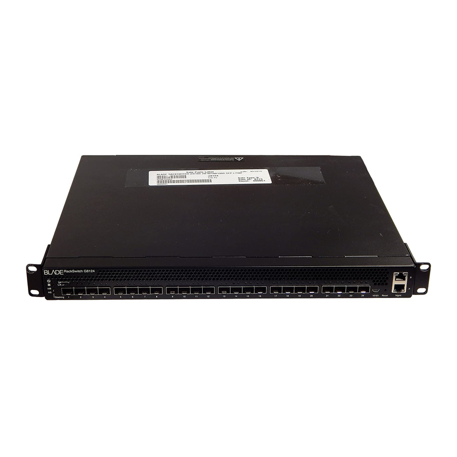
Page 12: Switch Ports
DC power source is connected, and lights steady when both DC power sources are connected. Switch Ports The RackSwitch G8124 switch ports and port options are described below. SFP+ Slots 24 Small Form-factor Pluggable (SFP+) slots are located on the front panel. These slots accept approved copper SFP transceivers, optical SFP+ transceivers, or Direct Attach Cables (DAC). - Page 13 SFP 1000BASE-T-SX Short Range Optical Transceiver BN-CKM-S-LX SFP 1000BASE-LX Long Range Fiber Transceiver The RackSwitch G8124 accepts any SFP+ Direct Attach Cable that complies to the MSA specification. 10/100/1000Base-T Ports Two 10/100/1000BaseT ports (RJ-45) are located on the front panel. These management ports support in-line management and Control Plane Stacking.
-
Page 14: Console Port
Pin 1 Pin 4 D9 Pins 1, 4, and 6 are connected Pin 6 Pin 7 Pin 8 D9 pin 7 is connected to D9 pin 8 Shell Braid Shell Chapter 1: RackSwitch G8124 Description and Specifications BPP-00018-01, December 2009... -
Page 15: Leds
Blink Green Blink Green Power Supplies OK Solid Green Power Supply Failure Blink Green Fans OK Solid Green Fan Failure Blink Green Stack Master Stack Backup/Member Stack Error Non-Stack Member BPP-00018-01, December 2009 Chapter 1: RackSwitch G8124 Description and Specifications... - Page 16 Status LEDs for the RJ-45 ports are described in the following table. Table 7 RJ-45 LEDs Status Solid Green Blink Green Link Valid Link Activity No Link Speed 100/1000Mbps 10Mbps Chapter 1: RackSwitch G8124 Description and Specifications BPP-00018-01, December 2009...
-
Page 17: Technical Specifications
RackSwitch G8124 Installation Guide Technical Specifications This section provides specifications for the RackSwitch G8124. Physical Characteristics Physical characteristics of the RackSwitch G8124F/G81240R switch unit are listed in the following table. Table 8 Physical Characteristics Specification G8124F G8124R Dimensions (H x W x D) 1.73 x 17.3 x 15.0 in. -
Page 18: Power Specifications
15A (typical) Table 11 DC Power Specifications Specification Measurement Number of power supplies 2 (1+1 redundant) Input Voltage 42VDC-60VDC 48VDC Nominal Input Current 5.2 A Maximum Power supply output power 250W Chapter 1: RackSwitch G8124 Description and Specifications BPP-00018-01, December 2009... -
Page 19: Ordering Information
RackSwitch G8124 Installation Guide Ordering Information The following table lists the parts that you can order for the RackSwitch G8124 product family. Table 12 RackSwitch G8124 Ordering Information Part number Description Switch BN-8124F-BDL G8124F 24-port GbE Switch (front-to-rear airflow) BN-8124R-BDL... - Page 20 RackSwitch G8124 Installation Guide Chapter 1: RackSwitch G8124 Description and Specifications BPP-00018-01, December 2009...
-
Page 21: Chapter 2: Installing The Rackswitch G8124
HAPTER Installing the RackSwitch G8124 This chapter describes how to install and initialize the RackSwitch G8124. Required Tools You need the following tools or equipment to successfully accomplish the installation procedures in this document: Standard flat-blade screwdriver #2 Phillips screwdriver... -
Page 22: Environmental Requirements
RackSwitch G8124 Installation Guide Environmental Requirements This section describes the basic environmental requirements for the RackSwitch G8124. Make sure the location where you install the switch meets the following requirements: Install the switch unit in a dry, clean, well-ventilated area. -
Page 23: Preventing Electrostatic Discharge
Do not touch connector pins. Installing the RackSwitch G8124 in a Standard Equipment Rack This section describes how to install the RackSwitch G8124 in a standard 19-inch equipment rack. For information about mounting the G8124 in other rack types, refer to the following sections: “Installing the RackSwitch G8124 in an iDataPlex Rack”... - Page 24 Use mounting brackets to secure each device to the rack. Perform the following steps to mount the RackSwitch G8124. Use the M4 screws to attach a mounting bracket to each side of the switch. Torque the screws to approximately 30 inch-pounds (3.5 Nm).
- Page 25 Slide the switch into the rack as illustrated. Figure 6 Rack-mounting the Switch Unit Use M6 screws, washers, and clip nuts to secure the switch unit to the rack. Torque the screws to approximately 30 inch-pounds (3.5 Nm). BPP-00018-01, December 2009 Chapter 2: Installing the RackSwitch G8124...
-
Page 26: Installing The Rackswitch G8124 In An Idataplex Rack
Installing the RackSwitch G8124 in an iDataPlex Rack This section provides general information about installing the RackSwitch G8124 in an IBM iDataPlex rack. The iDataPlex mounting kit allows the switch to be mounted either vertically or horizontally. For information about mounting the G8124 in other rack types, refer to the following sections: “Installing the RackSwitch G8124 in a Standard Equipment Rack”... - Page 27 RackSwitch G8124 Installation Guide Perform the following steps to mount the RackSwitch G8124 into an iDataPlex rack. Use the M4 screws to attach front and rear mounting brackets to each side of the switch unit. Torque the screws to approximately 30 inch-pounds (3.5 Nm).
- Page 28 M6 screws, washers, and clip nuts are used to mount the switch unit into the rack. Torque the screws to approximately 30 inch-pounds (3.5 Nm). Figure 9 Rack-Mounting the Switch Unit Chapter 2: Installing the RackSwitch G8124 BPP-00018-01, December 2009...
-
Page 29: Installing The Rackswitch G8124 In A 4-Post Rack
Installing the RackSwitch G8124 in a 4-post Rack This section provides general information about installing the RackSwitch G8124 in a 4-post rack, including the IBM e1350 - Type 1410. For information about mounting the G8124 in other rack types, refer to the following sections: “Installing the RackSwitch G8124 in a Standard Equipment Rack”... - Page 30 RackSwitch G8124 Installation Guide Perform the following steps to mount the RackSwitch G8124 into a standard 4-post rack. Use the M4 screws to attach a horizontal rail to each side of the switch. Torque the screws to approximately 10 inch-pounds (1.1 Nm).
- Page 31 The front mounting brackets and the rear mounting brackets are secured with M3 screws. Torque the screws to approximately 4 inch-pounds (0.5 Nm). Figure 13 Securing the Rear Bracket to the Front Bracket BPP-00018-01, December 2009 Chapter 2: Installing the RackSwitch G8124...
-
Page 32: Initializing The Rackswitch G8124
The console port’s terminal-emulation requirements are as follows: Default baud rate = 9,600 bps Character size = 8 characters Parity = none Stop bits = 1 Data bits = 8 Flow control = none Chapter 2: Installing the RackSwitch G8124 BPP-00018-01, December 2009... -
Page 33: Default Configuration
The default configuration is part of the software; it cannot be deleted or changed. The default settings allow the switch to perform basic functions with minimal effort by the system administrator. BPP-00018-01, December 2009 Chapter 2: Installing the RackSwitch G8124... -
Page 34: Configuring An Ip Interface
SNMP-based network management system or a Web browser. For more information about using the CLI, refer to the BLADE OS Command Reference for your RackSwitch G8124. Chapter 2: Installing the RackSwitch G8124 BPP-00018-01, December 2009... -
Page 35: Using The Boot Management Menu
To change the configuration block, press 2, and follow the screen prompts. To perform an Xmodem download, press 3 and follow the screen prompts. To exit the Boot Management menu, press 4. The boot process continues. BPP-00018-01, December 2009 Chapter 2: Installing the RackSwitch G8124... -
Page 36: Installing An Sfp Or Sfp+ Transceiver
RackSwitch G8124 Installation Guide Installing an SFP or SFP+ Transceiver The RackSwitch G8124 supports the following Small Form Factor Pluggable (SFP+) transceivers: SFP+ 10GBase-SR Short Range Transceiver (BN-CKM-SP-SR) SFP+ 10GBase-LR Long Range Optical Fiber Transceiver ( BN-CKM-SP-LR) SFP 1000BASE-T Copper Transceiver (BN-CKM-S-T) -
Page 37: Sfp Copper Transceiver
Connect the cable. To remove a SFP copper transceiver, disconnect the cable, and pull down the locking lever to release the transceiver. After you remove the transceiver, replace the safety cap. BPP-00018-01, December 2009 Chapter 2: Installing the RackSwitch G8124... -
Page 38: Troubleshooting
This section contains basic troubleshooting information. Use it to help resolve problems that may occur during installation and operation of your switch. If you have problems accessing the switch or working with switch software, refer to your RackSwitch G8124 Application Guide or Command Reference. -
Page 39: Switch Does Not Initialize (Boot)
Symptom: All the switch LEDs stay on, and the command prompt does not appear on the console. Solution: The operating system may have been damaged. Use the console port to perform a serial upgrade of the switch software. Refer to your Command Reference. BPP-00018-01, December 2009 Chapter 2: Installing the RackSwitch G8124... - Page 40 RackSwitch G8124 Installation Guide Chapter 2: Installing the RackSwitch G8124 BPP-00018-01, December 2009...
-
Page 41: Appendix A: Safety And Compliance Statements
PPENDIX Safety and Compliance Statements Safety Messages This section lists the safety messages that appear within this manual. Caution—To reduce the risk of electric shock, use only power cords that have a grounding path, and always connect the power cord to a properly grounded power outlet. —Pour réduire le risque de décharge électrique, employez seulement les cordons de TTENTION secteur qui ont un chemin fondant, et reliez toujours le cordon de secteur à... - Page 42 RackSwitch G8124 Installation Guide Warning—Electrical current from power, telephone, and communication cables is hazardous. To avoid a shock hazard: Do not connect or disconnect any cables or perform installation, maintenance, or reconfiguration of this product during an electrical storm. Connect the power supply only to a properly wired and grounded power source.
- Page 43 RackSwitch G8124 Installation Guide Advertencia—La corriente eléctrica de la energía, del teléfono, y de los cables de la comunicación es peligrosa. Para evitar un peligro de la descarga eléctrica: No conecte ni desconecte ninguna cables o no realice la instalación, el mantenimiento, o la reconfiguración de este producto durante una tormenta eléctrica.
- Page 44 RackSwitch G8124 Installation Guide Caution—Do not stack other devices on top of the switch unit in the rack. The mounting brackets cannot support multiple devices. Use mounting brackets to secure each device to the rack. —Ne posez aucun appareil supplémentaire sur le commutateur sans support additionnel.
- Page 45 RackSwitch G8124 Installation Guide Caution—Class 1 Laser Product Do not look directly into a fiber-optic transceiver or into the ends of fiber-optic cables. Fiber-optic transceivers and fiber-optic cable connected to a transceiver emit laser light that can damage your eyes.
-
Page 46: Compliance Statements
Properly shielded and grounded cables and connectors must be used in order to meet FCC emission limits. Blade Network Technologies, Inc. is not responsible for any radio or television interference caused by using other than recommended cables and connectors or by unauthorized changes or modifications to this equipment. -
Page 47: Industry Canada Class A Emission Compliance Statement
This product is in conformity with the protection requirements of EU Council Directive 2004/108/EC on the approximation of the laws of the Member States relating to electromagnetic compatibility. Blade Network Technologies, Inc. cannot accept responsibility for any failure to satisfy the protection requirements resulting from a nonrecommended modification of the product, including the fitting of unsupported option cards. - Page 48 RackSwitch G8124 Installation Guide NOM Statement (Mexico only) The following information is provided on the devices described in this document in compliance with the safety requirements of the Norma Oficial Méxicana (NOM): Exporter: Blade Network Technologies 2350 Mission College Blvd.
- Page 49 Observe the Regulatory Marking label on the back or bottom of each switch for specific certification information pertaining to this model. Each RackSwitch G8124 model is approved for shipment to/usage in Korea and is labelled as such, with all appropriate text and the appropriate MIC reference number.
- Page 50 RackSwitch G8124 Installation Guide Toxic / Hazardous Substances and Elements Table (RackSwitch G8124F/G8124R) o: Indicates that the content of the toxic and hazardous substance in all the homogeneous materials of the part is below the concentration limit requirement as described in SJ/T 11363-2006.
- Page 51 RackSwitch G8124 Installation Guide BPP-00018-01, December 2009 Appendix A: Safety and Compliance Statements...
- Page 52 RackSwitch G8124 Installation Guide 2350 Mission College Blvd. Suite 600 Santa Clara, CA 95054 www.bladenetwork.net Appendix A: Safety and Compliance Statements BPP-00018-01, December 2009...
Need help?
Do you have a question about the RackSwitch G8124 and is the answer not in the manual?
Questions and answers