
Summary of Contents for Northwind MAC1211
- Page 1 1291 Brummel Avenue Elk Grove Village, IL 60007 Phone 847-364-8600 Fax 847-364-8601...
-
Page 2: Table Of Contents
TABLE OF CONTENTS TOPIC PAGE General Description ……………………………….. Power Cord Information ……………………………….. Installation Instructions ……………………………….. Standard Features ……………………………….. ACRS (Advanced Condensate Removal System) ………… Electrical Panel & Components ……………………………. Blower-Motor Assemblies ……………………………... Plug/Receptacle Chart …………………………….. Optional Features ……………………………... Applications ……………………………... Replacement Part Procedure ……………………………... -
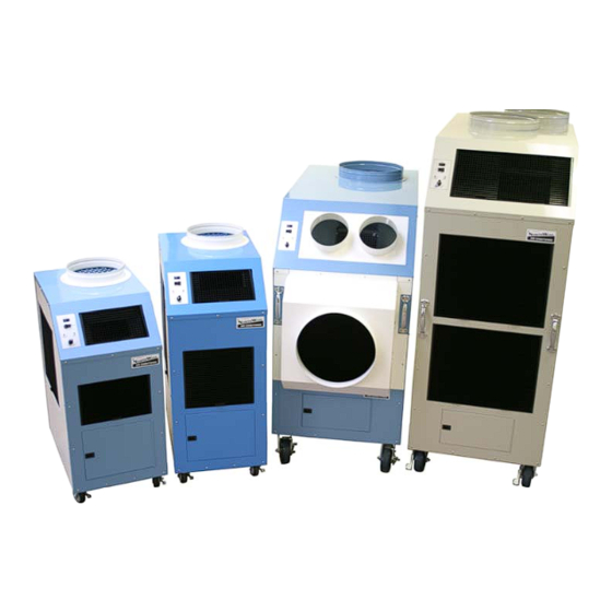
Page 3: General Description
NorthWind Portable Air-Cooled Air Conditioners are designed and built to cool a wide variety of applications by mov- ing air through a 12 ½ x 7 inch evaporator discharge grille (Models MAC1211/1811), 18 ½ x 8 (Models MAC3612/32), 22 x 11½ (Model MAC6012/32/34) and 23 x 11½ (Model MAC9032/34). These self-contained, port-... -
Page 4: Power Cord Information
LCDI POWER CORD & PLUG This air conditioner may be equipped with an LCDI (Leakage Current Detection and Interruption) power cord and plug as required by US National Electric Code 440.65. The cord consists of a length of shielded flexible cord with no termination on the load side and an LCDI attachment plug on the line side. -
Page 5: Standard Features
INSTALLATION GUIDELINES: This manual is used for guidance and does not form part of a contract. NorthWind, Inc. reserves the right to make technical changes without prior notice. Always place the unit on a level surface. The unit shall be installed in accordance with national and local wiring regulations. -
Page 6: Acrs (Advanced Condensate Removal System)
CONSTANT PRESSURE EXPANSION VALVE /FREEZE STAT/HOT GAS BYPASS Each NorthWind unit is provided with a constant pressure expansion valve, freeze stat or hot gas bypass to prevent frost formation on the evaporator coil. This is most useful when operating in high humidity conditions at low fan speeds and moderate to lower temperatures. - Page 7 CONDENSATE ALERT LIGHT, RED Every NorthWind unit is equipped with a red Condensate Alert light. The light is lit when one of two conditions ex- ists: 1) The condensate tank is full. 2) The condensate cannot be pumped out of the condensate pump. 3) This requires pushing the reset button in the unit’s cord storage compartment (MAC1211/1811) or behind the front access door...
-
Page 8: Electrical Panel & Components
EVAPORATOR FAN CYCLE SWITCH All of NorthWind’s units are equipped with an evaporator fan cycle switch. Located in the cord storage box (models MAC1211/1811) and behind the front access door (model MAC60/MAC90, when switched to “cycle” function, the evaporator blower turns on and off with the compressor. -
Page 9: Blower-Motor Assemblies
EVAPORATOR & CONDENSER BLOWER MOTOR ASSEMBLIES Each 1 and 1½ ton unit is equipped with a new technology external rotor, forward curved, squirrel cage blower for the evaporator and condenser sec- tions. The external rotor motor is totally enclosed, PSC, thermally protected, 2-speed, with sealed ball bearings, and dynamically balanced in 2 planes for reduced noise/vibration levels. -
Page 10: Plug/Receptacle Chart
SERVICE CORD Every NorthWind unit has a 10 foot long electrical service cord. On all required service cords, an electric protection device (LCDI/AFCI)* is included. This complies with the UL requirements issued August 1, 2004. There are no re- quirements for these devices on 3 phase units. -
Page 11: Optional Features
The NZ-5 is used on the MAC1211, 1811. It consists of 2, 5-inch nozzles with a compressed length of 16 inches and ap- proximate extended length of 24 inches. - Page 12 Condenser air plenums can substantially reduce air noise and increase options for solving difficult and unusual cooling applications. All NorthWind units use a dedicated, automatic, 2 speed condenser blower controlled by the “load” or pressure in the high side of the refrigerant system.
- Page 13 Evaporator air plenums can substantially reduce air noise and increase the number of options used for solving difficult and unusual cooling applications. All NorthWind units use a dedicated, automatic, 2 speed evaporator blower controlled by the fan speed switch mounted on the unit control panel. Another important topic to consider is the amount of duct that can be attached to a unit.
-
Page 14: Applications
ROOM AIR CONDITIONER NorthWind units can be used as room air conditioners to cool a room or confined space. This application requires using a CAP (Condenser Air Plenum) and a CDF (Condenser Duct Flange) to duct condenser air into the unit and duct condenser hot air out of the unit. -
Page 15: Replacement Part Procedure
REPLACEMENT PART PROCEDURES EVAPORATOR BLOWER DIRECT DRIVE Disconnect unit from power/unplug power cord. Remove screws to top, right & left side panel, and remove. Remove evaporator duct shroud. Cut, mark and strip electric wires from blower motor for re-connection later. Position top panel to permit blower removal. - Page 16 POWER READY or CONDENSATE ALERT LIGHT Disconnect unit from power/unplug power cord. Remove attaching screws that secure the top panel. Lift the top front panel about 6 inches to reveal the 2 wires that attach the light. The copper sensing tube for the thermostat will provide some resistance.
-
Page 17: Electrical Inspection/Repair
CONDENSER FAN CYCLE CONTROL Disconnect unit from power; unplug power cord. Remove right side panel of unit. Remove and mark 2 wires on terminals of cycle switch to assure correct reconnection. Using a 9/16 flare tube wrench, remove switch from schrader access valve. A small, DeMinimus release of refrigerant may occur when components are separated. -
Page 18: Troubleshooting Guide
TROUBLESHOOTING GUIDE The following procedures are recommended when correcting the indicated problems. Routine clean- ing and maintenance can be performed by anyone. Service and repair should be performed only by a qualified refrigeration service person. PROBLEM: THE ENTIRE UNIT DOES NOT RUN. Green light not lit. CAUSE: POWER INTERRUPTION REMEDY:... - Page 19 PROBLEM: COMPRESSOR STARTS & RUNS, BUT EVAPORATOR FAN DOES NOT RUN. 1. CAUSE: Loose wires on fan speed switch or fan cycle switch. REMEDY: Check for loose wires, repair/replace as required. 2. CAUSE: Defective fan speed switch. REMEDY: Remove/replace fan switch. 3.
-
Page 20: Preventive Maintenance Guide
If a combination of vertical height and horizontal drain line exceeds 20 feet of water pressure drop, problems will occur. PREVENTIVE MAINTENANCE GUIDE All NorthWind units are designed to last and give maximum performance/reliability with minimum maintenance. To extend the life of the unit, a few simple procedures must be performed. BLOWER MOTORS The external rotor motor and blower wheel is a balanced/bolted assembly requiring no maintenance. -
Page 21: Inside View Belt Drive Units (Mac60-90)
INSIDE VIEW OF MAC 60 Heavy duty drive com- Condenser discharge ponents utilizing tapered Evaporator discharge shroud. Helps attenuate pulley bushings rather shroud. Helps attenuate air noise by creating a air noise by creating a small plenum. small plenum. Heavy duty Heavy duty belt drive belt drive condenser blower with... -
Page 22: Inside View Direct Drive Units (Mac12-18)
INSIDE VIEW OF MAC1811 12 gauge support beam Condenser coil 2 speed Evaporator Blower (external rotor) Fan Cycle Condenser blower (external rotor) Evaporator Coil Corner post Constant Pressure expansion valve Thermostatic Liquid line drier expansion valve 12 gauge support Condensate tank Compressor Accumulator Electrical box... -
Page 23: Wiring Diagrams
MAC6012 WIRING DIAGRAM June 4, 2007 208/230/1 POWER TERMINAL GROUND CONDENSER BLOWER MOTOR CONDENSER CONTACTOR 208/230 CONDENSER FAN SWITCH 24 V EVAP FAN LOW HIGH CONTACTOR 2-SPEED EVAPORATOR EVAPORATOR FAN SPEED BLOWER MOTOR CONSTANT CONDENSATE PUMP CYCLE PUMP FLOAT EVAP FAN HIGH SWITCH CONTACTOR TIME... - Page 24 MAC6012 WIRING DIAGRAM Sep 12, 2007 208/230/1 WITH REMOTE THERMOSTAT POWER TERMINAL GROUND CONDENSER BLOWER MOTOR CONDENSER CONTACTOR 208/230 CONDENSER FAN SWITCH 24 V EVAP FAN LOW HIGH CONTACTOR 2-SPEED EVAPORATOR EVAPORATOR FAN SPEED BLOWER MOTOR CONSTANT CONDENSATE PUMP CYCLE PUMP FLOAT EVAP FAN HIGH...
- Page 25 MAC6032/9032 WIRING DIAGRAM 208-230/3/60HZ April 2, 2007 POWER GROUND TERMINAL CONDENSER PHASE MONITOR BLOWER MOTOR CONDENSER CONTACTOR 208/230 CONDENSER FAN SWITCH 24 V EVAP FAN LOW HIGH CONTACTOR 2-SPEED EVAPORATOR EVAPORATOR FAN SPEED BLOWER MOTOR CONSTANT CONDENSATE PUMP CYCLE PUMP FLOAT EVAP FAN HIGH SWITCH...
- Page 26 MAC6032/9032 WIRING DIAGRAM 208/230/3/60HZ REMOTE THERMOSTAT OPTION September 10, 2007 POWER GROUND TERMINAL CONDENSER PHASE MONITOR BLOWER MOTOR CONDENSER CONTACTOR 208/230 CONDENSER FAN SWITCH 24 V EVAP FAN LOW HIGH CONTACTOR 2-SPEED EVAPORATOR EVAPORATOR FAN SPEED BLOWER MOTOR CONSTANT CONDENSATE PUMP CYCLE PUMP...
- Page 27 MAC6034-9034 WIRING DIAGRAM 440/460/3/60HZ June 16, 2007 POWER GROUND TERMINAL 440/460/3/60HZ 24 V PHASE MONITOR CONDENSER 460 V BLOWER MOTOR CONDENSER CONTACTOR 460 V CONDENSER FAN SWITCH 230 V EVAP FAN LOW HIGH CONTACTOR 2-SPEED EVAPORATOR EVAPORATOR FAN SPEED BLOWER MOTOR CONSTANT CONDENSATE...
- Page 28 MAC6034-9034 WIRING DIAGRAM 440/460/3/60HZ WITH REMOTE THERMOSTAT June 16, 2007 POWER GROUND TERMINAL 440/460/3/60HZ 24 V PHASE MONITOR CONDENSER 460 V BLOWER MOTOR CONDENSER CONTACTOR 460 V CONDENSER FAN SWITCH 230 V EVAP FAN LOW HIGH CONTACTOR 2-SPEED EVAPORATOR EVAPORATOR FAN SPEED BLOWER MOTOR...
- Page 29 MAC1211-1811 WIRING DIAGRAM October 16, 2006 120/1/60HZ EVAPORATOR EVAPORATOR FAN RELAY BLOWER MOTOR POWER POWER BROWN PLUG CORD 120/1/60 BLACK BLUE WHITE CONDENSER BLOWER MOTOR BROWN 120/1/60 BLACK BLUE CONDENSER FAN SPEED 24 V WHITE COMPRESSOR CONTACTOR CONDENSATE START PUMP...
-
Page 30: Wiring Diagrams
MAC1211-1811 WIRING DIAGRAM October 16, 2006 120/1/60HZ WITH REMOTE THERMOSTAT EVAPORATOR EVAPORATOR FAN RELAY BLOWER MOTOR POWER POWER BROWN PLUG CORD 120/1/60 BLACK BLUE WHITE CONDENSER BLOWER MOTOR BROWN 120/1/60 BLACK BLUE CONDENSER FAN SPEED WHITE 24 V COMPRESSOR CONTACTOR... -
Page 31: Piping Schematic
October 18, 2006 HIGH PRESSURE SWITCH CONDENSER COIL CONDENSER BLOWER SPEED SWITCH ACCESS ACCESS PORT PORT SUCTION COMPRESSOR ACCUMULATOR LIQUID LINE FILTER DRYER EVAPORATOR 1/4 OD EXTERNAL COIL EQUALIZER LINE THERMOSTATIC EXPANSION VALVE or CAPILLARY TUBE CONSTANT PRESSURE EXPANSION VALVE or FREEZE CONTROL... -
Page 33: Remote Thermostat Option
REMOTE THERMOSTAT OPTION All MAC models are capable of being factory equipped to operate with a remote located 24 volt thermostat. When this option is used, the unit’s thermostat remains in the unit but no longer controls. Control is transferred to the re- mote thermostat through the remote terminal block located behind the electrical access panel. - Page 35 DISCLAIMER All information and technical specifications presented in this service/installation manual are subject to change or modification without prior notification of any kind.
-
Page 36: Warranty
LIMITED WARRANTY NorthWind, Inc. (the manufacturer) warrants to the origi- 5) To any workmanship of the installer of the nal owner that the product will be free from defects in ma- product. terial or workmanship for a period not to exceed one (1) year from date of installation.
Need help?
Do you have a question about the MAC1211 and is the answer not in the manual?
Questions and answers