
Related Manuals for Centurion TB-CN2R1

Summary of Contents for Centurion TB-CN2R1
- Page 1 SYSTEM CONTROLLER TB-CN2R1 (2 AXIS STANDARD) TB-CN3R1 (3 AXIS STANDARD) TB-CN3R1W (3 AXIS WEB) Instruction Manual TB-CN2R1 (2 AXIS STANDARD) TB-CN3R1 (3 AXIS STANDARD) TB-CN3R1W (3 AXIS WEB) Rev 2.0...
-
Page 2: Table Of Contents
CONTENTS WHAT'S IN THE BOX WARNING & CAUTION GENERAL DESCRIPTIONS A. GENERAL DESCRIPTIONS B. FEATURES INSTALLATION PART NAMES & FUNCTIONS A. GENERAL DESCRIPTIONS B. PART NAME & FUNTIONS (REAR SIDE) C. DRAWING OF CONSOLE DESK ACCESSING TO THE CAMERA MENU A. -
Page 3: Warning & Caution
WARNING & CAUTION WARNING TO REDUCE THE RISK OF FIRE OR ELECTRIC SHOCK, DO NOT EXPOSE THIS PRODUCT TO RAIN OR MOISTURE. DO NOT INSERT ANY METALLIC OBJECT THROUGH THE VENTILATIONGRILLS OR OTHER OPENINGS ON THE EQUIPMENT. CAUTION CAUTION RISK OF ELECTRIC SHOCK DO NOT OPEN CAUTION: TO REDUCE THE RISK OF ELECTRIC SHOCK, DO NOT REMOVE COVER(OR BACK). -
Page 4: Fcc Compliance Statement
FCC COMPLIANCE STATEMENT INFORMATION TO THE USER : THIS EQUIPMENT HAS BEEN TESTED AND FOUND TO COMPLY WITH THE LIMITS FOR A CLASS A DIGITAL DEVICE, PURSUANT TO PART 15 OF THE FCC RULES. THESE LIMITS ARE DESIGNED TO PROVIDE REASONABLE PROTECTION AGAINST HARMFUL INTERFERENCE WHEN THE EQUIPMENT IS OPERATED IN A COMMERCIAL ENVIRONMENT. -
Page 5: General Descriptions
GENERAL DESCRIPTIONS GENERAL DESCRIPTIONS TB-CN2R1, TB-CN3R1(3 AXIS STANDARD) AND TB-CN3R1W(3 AXIS WEB ) are pan/tilt controller and it allows operator to use the functions easily. This controls camera functions such as pan, tilt, zoom, focus and DVR control. This saves and calls camera preset positions. -
Page 6: Installation
INSTALLATION 1. Jump 2. Junction Box 3. LAN 4. DATA 5. Cable 6. DATA 7. Terminal Block 8. D-SUB Jack (9 pin) lave Setting Jump Junction Box LAN Cable Connection RJ45 Modular Jack (Data Input) Modular Cable - 8pin Junction Box to Key Board RJ45 Modular Jack (Data Output) Terminal Block (To PTZ Communication Wire) - Page 7 12V power to DC jack. Open the Junction Box cover and set slave interface jumps (LAN,RS232) Default setting for TB-CN2R1 (2 Axis standard) and TB-CN3R1(3 Axis standard) is by RS-232 and TB-CB3R1W (3 Axis WEB) is by web. Connect CAM1(RS485(+), RS485(-)) on Junction Box Terminal and communication jack on PTZ camera.
-
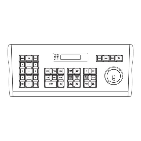
Page 8: Part Names & Functions
PART NAME & FUNCTIONS PART NAME & FUNCTIONS 17 18 16 14 22 20 1. LCD Display : Displays numeric input, 14. FUNC : Function key system status, function status, general 15. ENTER : Enter key (DVR) status, etc 16. SEL : Selects Key (DVR and Key Board 2. -
Page 9: Part Name & Funtions (Rear Side)
PART NAME & FUNCTIONS PART NAME & FUNCTIONS(REAR SIDE) DATA Data out port (connector to communication and Power) DRAWING OF CONSOLE DESK 90mm 30mm 30mm 155mm 365mm... -
Page 10: Accessing To The Camera Menu
ACCESSING TO THE CAMERA MENU This function is only for the PTZ camera. DISPLAY LCD WINDOW A-1. Initial display Show the selected unit (Camera or DVR) CAM : 001 2400 bps Show the selected unit address No. (001 ~ 255) Show the selected baud rate (2400/4800/9600 bps) STAND BY.. -
Page 11: Easy Preset Save And Calls
ACCESSING TO THE CAMERA MENU Easy preset save and calls (in case of cam 1/2400 bps) C-1. How to save preset 1 or 2 - After pushing no.1 or 2, hold PRST for about 2 seconds) CAM 001 2400 bps PRST à... -
Page 12: How To Use Autoscan Function
ACCESSING TO THE CAMERA MENU How to use AUTOSCAN function F-1. How to use autoscan DVR 001 2400 bps SCAN à Scan How to use ABB Key - ABB key is a short key to move to a certain preset easily when you use many cameras. -
Page 13: How To Use Setup Menu
HOW TO USE SETUP MENU When you change the setting value of setup menu, you should enter "5. Save and Exit" How to go to setup menu : After pushing no. key 11, hold SEL key for over 3 seconds). How to use setup menu A-1. -
Page 14: Specification
SPECIFICATION MODEL TB-CN2R1 TB-CN3R1 TB-CN3R1W MASTER : RS485 (2400bps, 4800bps, 9600bps) Communication SLAVE : RS232 (2400bps, 4800bps, 9600bps) LAN : (TB-CN3R1W Only) (2400bps, 4800bps, 9600bps) Joystic 2-Axis 3-Axis, Zoom IN/OUT available Power Consumption DC 12V, 110mA Display Type 16 x 2 Character LCD, With Blue Backlight... -
Page 15: Dimension
DIMENSIONS... - Page 16 Made in Korea April 2006...
Need help?
Do you have a question about the TB-CN2R1 and is the answer not in the manual?
Questions and answers