Table of Contents
Advertisement
WARNING
Improper installation, adjustment, alteration,
service or maintenance can cause property
damage, injury or death, and could cause
exposure to substances which have been
determined by various state agencies to cause
cancer, birth defects or other reproductive
harm. Read the installation, operating and
maintenance instructions thoroughly before
installing or servicing this equipment.
CAUTION
To prevent premature heat exchanger failure
do not locate ANY gas-fired units in areas
where chlorinated, halogenated or acid
vapors are present in the atmosphere.
FOR YOUR SAFETY
WHAT TO DO IF YOU SMELL GAS:
1. Open windows.
2. Do not try to light any appliance.
3. Do not touch any electrical switch; do not
use any phone in your building.
4. Immediately call your gas supplier from
a neighbor's phone. Follow the gas
supplier's instructions. If you can not reach
your gas supplier, call your fire department.
PLEASE BE SURE TO LEAVE IT WITH THE OWNER WHEN YOU LEAVE THE JOB.
Hamilton Home Products, Inc.
INSTALLATION AND SERVICE MANUAL
THIS MANUAL IS THE PROPERTY OF THE OWNER.
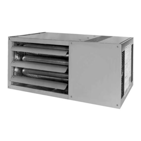
gas-fired unit heaters
All models approved for use in California by the CEC, in New
York by the MEA division, and in Massachusetts. Unit heater
is certified for residential and commercial applications.
FOR YOUR SAFETY
The use and storage of gasoline or other
flammable vapors and liquids in open
containers in the vicinity of this appliance
is hazardous.
IMPORTANT
The use of this manual is specifically
intended for a qualified installation and
service agency. All installation and service
of these units must be performed by a
qualified installation and service agency.
Inspection on Arrival
1.
Inspect unit upon arrival. .
2.
Check rating plate on unit to verify that power supply meets
available electric power at the point of installation.
3.
Inspect unit upon arrival for conformance with description of
product ordered (including specifications where applicable).
For technical assistance and Warranty Administration,
contact Hamilton Home Products at 1.800.879.0123. Do not
return equipment to the home center.
Table of Contents
Inspection on Arrival . . . . . . . . . . . . . . . . . . . . . . . . . . . . . . . . .1
Special Precautions . . . . . . . . . . . . . . . . . . . . . . . . . . . . . . . . . .2
SI (Metric) Conversion Factors . . . . . . . . . . . . . . . . . . . . . . . . .3
Unit Location . . . . . . . . . . . . . . . . . . . . . . . . . . . . . . . . . . . . . . .3
Combustible Material and Service Clearances . . . . . . . . .3
Unit Mounting . . . . . . . . . . . . . . . . . . . . . . . . . . . . . . . . . . .4
Unit Installation . . . . . . . . . . . . . . . . . . . . . . . . . . . . . . . . . . . . .6
Venting . . . . . . . . . . . . . . . . . . . . . . . . . . . . . . . . . . . . . . . .5
Gas Connections . . . . . . . . . . . . . . . . . . . . . . . . . . . . . . .10
Electrical Connections . . . . . . . . . . . . . . . . . . . . . . . . . . .11
Checking Input Rate . . . . . . . . . . . . . . . . . . . . . . . . . . . . .12
Unit Components . . . . . . . . . . . . . . . . . . . . . . . . . . . . . . . . . . .14
Dimensions . . . . . . . . . . . . . . . . . . . . . . . . . . . . . . . . . . . . . . .16
Service/Trouble Shooting . . . . . . . . . . . . . . . . . . . . . . . . . . . .17
Wiring . . . . . . . . . . . . . . . . . . . . . . . . . . . . . . . . . . . . . . . . . . .21
Warranty . . . . . . . . . . . . . . . . . . . . . . . . . . . . . . . . . . . . . . . . .35
VHHP6-576.5
Part 5H76253 Rev. E
March, 2004
model WGH
Advertisement
Table of Contents

Summary of Contents for Hamilton Home Products WGH
-
Page 1: Table Of Contents
(including specifications where applicable). CAUTION For technical assistance and Warranty Administration, contact Hamilton Home Products at 1.800.879.0123. Do not To prevent premature heat exchanger failure return equipment to the home center. do not locate ANY gas-fired units in areas... -
Page 2: Special Precautions
SPECIAL PRECAUTIONS/TABLE OF CONTENTS SPECIAL PRECAUTIONS THE INSTALLATION AND MAINTENANCE INSTRUCTIONS IN THIS CAUTION MANUAL MUST BE FOLLOWED TO PROVIDE SAFE, EFFICIENT AND TROUBLE-FREE OPERATION. IN ADDITION, PARTICULAR 1. Installation must conform with local building codes or in the CARE MUST BE EXERCISED REGARDING THE SPECIAL absence of local codes, with Part 7, Venting of Equipment, PRECAUTIONS LISTED BELOW. -
Page 3: Si (Metric) Conversion Factors
SPECIAL PRECAUTIONS / SI (METRIC) CONVERSION FACTORS / UNIT LOCATION This unit is certified with the controls furnished. For CAUTION replacements parts, please order according to the replacement parts list on serial plate. Always know your model and serial numbers. The right is reserved to 18. -
Page 4: Unit Mounting
UNIT LOCATION / UNIT MOUNTING UNIT SUSPENSION 3. Be sure the structural support at the unit location site is CAUTION adequate to support the weight of the unit. For proper operation the unit must be installed in a level horizontal 1. -
Page 5: Venting
INSTALLATION Venting Instructions 1. All vertically vented heaters are category I venting. Venting All horizontally vented heaters are category I or III depending on venting. For a unit to be classified vertical, WARNING the horizontal run may not exceed 75% of the vertical rise. 2. -
Page 6: Unit Installation
INSTALLATION Figure 6.2 Vertical Venting Through Flat Roof 15. A unit located within an unoccupied attic or concealed space shall not be vented with single wall vent pipe. 2' Min 16. Single wall vent pipe must not pass through any attic, inside wall, concealed space, or floor. - Page 7 A. All residential, horizontally vented category III heaters Figure 7.1 must be vented with an agency certified category III Horizontal Category III Venting with Upward Pitch venting system. Agency certified category III venting systems are available from your local vent pipe Specified Terminal (See No.4, page7) distributor.
- Page 8 INSTALLATION The vent terminal for a horizontal category I vent may be Figure 8.1 either a standard vent TEE, a Gary Steel 1092 or a Breidert Horizontal Category I Venting -TEE With Upward Pitch Type L style cap. The maximum number of elbows, slope of the horizontal section, and minimum vertical rise from horizontal vent pipe for each configuration is listed in Table Exterior wall...
- Page 9 INSTALLATION Figure 9.1 Figure 9.2 Horizontal Category I Venting - Clearance to Eave Horizontal Category I Venting - TEE With Downward Pitch Exterior wall 1/4" Slope down towards termination Vent tee Listed thimble 12" Min 24" Max 6" Min 4" Min Listed thimble 12"...
-
Page 10: Gas Connections
determine the cubic feet per hour (CFH) for the type of gas INSTALLATION and size of unit to be installed. Using this CFH value and Gas Connections the length of pipe necessary, determine the pipe diameter from Table 10.1. Where several units are served by the WARNING same main, the total capacity, CFH and length of main must be considered. -
Page 11: Electrical Connections
INSTALLATION B. BEFORE OPERATING smell all around the appliance area Wiring for gas. Be sure to smell next to the floor because some gas is heavier than air and will settle on the floor. WARNING WHAT TO DO IF YOU SMELL GAS 1. -
Page 12: Checking Input Rate
proceed down the cu. ft. column to 100 cu. ft. per hr. and then CHECKING INPUT RATE horizontally to the left to determine a time of 36 seconds for one revolution of the dial. Similarly, if the 1/2 cu. ft. dial is used, we determine a time of 18 seconds for one revolution at the C C A A U U T T I I O O N N required input. - Page 13 CHECKING INPUT RATE inlet pressure at unit. The inlet pressure should be 6-7" W.C. pressure on natural gas and 12-14" W.C. on propane gas. After adjustment, move gas control knob (or lever) to OFF and replace 1/8" pipe plug. With plug in place follow the lighting instructions to put unit back in service.
-
Page 14: Unit Components
UNIT COMPONENTS Figure 14.1 Major Gas, Electrical Service, Safety and Other Components Field Supplied Gas Pipe Common Replacement Parts Mounting Brackets Gas Orifices Heat Exchanger Hot Surface Igniter Combination Gas (Hidden) Control Electrical Access Holes Diagnostic Limit Control Codes (Hidden) Pressure Switch Adjustable... - Page 15 UNIT COMPONENTS Figure 15.1 Unit Heater Rear View Electrical Access Mounting Brackets Holes Fingerproof Fanguard Fan Motor Access Panel with Vent Pipe Connection Gas Pipe Hole Lighting / Operating (Gas Pipe Field Supplied) Instructions Figure 15.2 Unit Heater in Standard Mounting Configuration (from factory this orientation - brackets not attached) Figure 15.3 Unit Heater Turned 180°...
-
Page 16: Dimensions
DIMENSIONS / GENERAL PERFORMANCE DATA Mounting Holes Typ 5/16 x 2.5" Long Adjustable Deflector Blades Opening Power Venter Vent Pipe Connection Mounting 1.00 Brackets Electrical Access Side Connections Dimensions (inches) Connection Model Size 26.8 26.8 26.8 26.8 12.2 12.2 18.0 18.0 16.5 16.5... -
Page 17: Service/Trouble Shooting
CONTROL OPERATING SEQUENCE For Hot Surface Ignition Upon a call for heat from the thermostat, power is supplied to the power exhauster motor. The unit will go through a purge period and then the hot surface igniter will be energized. After the igniter has warmed up, the main valve in the combination control valve will open to allow gas to flow to the burners. - Page 18 SERVICE / MAINTENANCE / TROUBLESHOOTING Service Instructions – Safety Devices WARNING Limit Control (Overheat Switch) When servicing or repairing of this equipment, use only The limit control, mounted in airstream (on access side), will factory- approved service replacement parts. A complete shut off the gas supply to the burners in the event of replacement parts list may be obtained by contacting the overheating.
- Page 19 System lockout FOR SERVICE If a qualified service person cannot solve the problem, consult your local gas company or local Hamilton Home Products, Inc. representative. When servicing, repairing or replacing parts on these units always give the complete Model Number and Serial Number from the unit rating plate.
- Page 20 SERVICE / MAINTENANCE / TROUBLESHOOTING Table 20.1 Troubleshooting TROUBLE POSSIBLE CAUSE POSSIBLE REMEDY Unit does nothing. 1. Power supply is off Turn on main power. 2. No 24V power to thermostat 2 a. Check control transformer b. If failed transformer - check thermostat wire gage and length 3.
-
Page 21: Wiring
UNIT WIRING serial number. For example, a unit with the serial number Wiring Diagram Selection "30011023601-0981" has the 5 through the 7 digits as 102 as Since internal or factory wiring may vary depending on controls shown underlined above. Match the series ID from the unit manufacturer, the wiring diagrams must be selected with the serial plate with the series ID listed in the heading of the series identity number when installing, servicing, or... - Page 22 UNIT WIRING Figure 22.1 Unit Heater Wiring Diagram (Series 103) UNIT HEATER WIRING DIAGRAM Wiring Legend Line Factory Field 115V/60Hz/1Ø Power (BK) Circuit Breaker Wire Nut (By Others) Shown TD Relay Flame 115V/60Hz/1Ø Power Sensor Circuit Breaker (By Others) Motor Motor GR(G) Combination...
- Page 23 HAMILTON HOME PRODUCTS, INC. LIMITED WARRANTY (Residential Use Only) WHAT THIS WARRANTY COVERS WHAT HAMILTON WILL DO TO CORRECT ANY PART OR EQUIPMENT FAILURES DURING THE WARRANTY PERIOD This warranty covers all defects in material and workmanship in your Hamilton unit heater, when used for your home or garage.
-
Page 24: Commercial Warranty
WITHIN ONE YEAR FROM DATE OF RESALE BY BUYER IN ANY BUYER. Hamilton Home Products, Inc. has a continuous product improvement program; it reserves the right to change design and specifications without notice. • FOR RESIDENTIAL USE SEE LIMITED CONSUMER WARRANTY ON PREVIOUS PAGE.
Need help?
Do you have a question about the WGH and is the answer not in the manual?
Questions and answers