Table of Contents
Advertisement
I
Please read this manual and the enclosed safety materials carefully!
I
Fasten the manual near the garage door after installation.
I
The door WILL NOT CLOSE unless the Protector System
aligned.
I
Periodic checks of the opener are required to ensure safe operation.
I
The model number label is located on the back of your opener.
Garage Door Opener
Model 642-2MM
1/2 HP
For Residential Use Only
Owner's Manual
Made exclusively for
Master Mechanic
Chicago, IL 60614
®
is connected and properly
®
Advertisement
Table of Contents

Subscribe to Our Youtube Channel
Summary of Contents for master mechanic Security+ 642-2MM
- Page 1 Made exclusively for Master Mechanic Chicago, IL 60614 ® Garage Door Opener Model 642-2MM 1/2 HP For Residential Use Only Owner’s Manual Please read this manual and the enclosed safety materials carefully! Fasten the manual near the garage door after installation.
-
Page 2: Table Of Contents
Contents Safety alert symbol review..........2 Complete the safety reversing sensor installation..22 Safety information, precautions, tools ......3 Install the lights and lens ..........23 Testing your garage door for binding & balance ..3 Attach the manual release rope and handle....23 Carton inventory ............4 Fasten the door bracket (sectional door) ....24 Hardware inventory............5 Fasten the door bracket (one-piece door)....25... -
Page 3: Safety Information, Precautions, Tools
Safety Information, Precautions, Tools WARNING CAUTION CAUTION An unbalanced garage door might not reverse when To avoid damage to the garage door and opener, disable required and someone under the door could be seriously locks before installing and operating the opener. Use a injured or killed. -
Page 4: Carton Inventory
Carton Inventory Your garage door opener is packaged in one carton which contains the power unit and all parts illustrated below. If anything is missing, carefully check the packing material. Parts may be "stuck" in the foam. KEEP THE FOAM INTACT (see page 10). -
Page 5: Hardware Inventory
Hardware Separate all hardware from the packages in the rail carton and the opener carton and group as shown below, for the assembly and installation procedures. Assembly Hardware Bolt Lock Nut 1/4" - 20 x 5/8" 1/4-20x1-3/4" (8) 1/4"-20 x 7/16 (12) Sprocket Coupling Sleeve Hex Screw (4) Installation Hardware... -
Page 6: Illustration Of Sectional Door Installation
SECTIONAL Door Installation Before you begin, survey your garage area to see whether any of the conditions below apply to your installation.You may find it helpful to refer back to this page as you proceed with the installation of your opener. FINISHED CEILING Support bracket &... -
Page 7: Illustration Of One-Piece Door Installation
ONE-PIECE Door Installation Before you begin, survey your garage area to see whether any of the conditions below apply to your installation. You may find it helpful to refer back to this page as you proceed with the installation of your opener. Header Wall One-Piece Door without Track... -
Page 8: Assembly Section: Pages
Assembly Section: Pages 8 - 11 ASSEMBLY STEP 1 To avoid installation difficulties, do not run the garage Assemble the Rail door opener until instructed to do so. Straight Door Arm Extend End Rails Remove Outward Cardboard Packing Rail Center Support Rail Braces... - Page 9 ASSEMBLY STEP 1 (Continued) Assemble the Rail 4. Beginning with the sprocket end, straighten the two 7. Keeping the rail straight and on a level surface, grasp rail sections so that the screw rod is in a straight line at the screw rods on each side of the remaining joint and the joint.
-
Page 10: Fasten Rail To Power Unit
ASSEMBLY STEP 2 Fasten the Rail To the Power Unit and Install the Trolley NOTE: To aid in assembly and installation, replace /7/94 the foam packing around the power unit. Remove it after Installation Step 5. • Working on a level surface, align the rail assembly with Rail/Power Unit Power Unit Sprocket... -
Page 11: Attach The Rail Brackets
ASSEMBLY STEP 3 Attach the Rail Brackets 1/4"-20 • Align rail brackets to end of rail assembly, as shown. Rail Lock Nuts Brackets • Insert two 1/4"-20 x 5/8" hex screws and lock nuts. Tighten securely with a 7/16" socket. Hardware Shown Actual Size 1/4"... -
Page 12: Installation Section: Pages
Installation Section: Pages 12 – 27 Installation Step 1 WARNING Determine Header Bracket Location If the header bracket is not rigidly fastened to a Installation procedures vary according to garage structural support on the header wall or ceiling, the door types. Follow the instructions which apply to safety reverse system may not work properly (see your door. -
Page 13: One-Piece Door
ONE-PIECE Door Without Track Read the Safety Instructions on page 12. They also apply to doors without tracks. Unfinished • Close the door and mark the inside Header Wall Ceiling Vertical vertical centerline of your garage door. Centerline Extend the line onto the header wall above door. -
Page 14: Install The Header Bracket
Installation Step 2 Install the Header Bracket You can attach the header bracket either to the wall above the garage door, or to the ceiling. Follow the instructions which will work best for your particular requirements. Fastening the Header Bracket to the Ceiling Fastening the Header Bracket to the Wall •... -
Page 15: Attach The Rail To The Header Bracket
Installation Step 3 Attach the Rail to the Header Bracket • Position the opener on the garage floor below the header bracket. Use packing material as a protective base. If the door spring is in the way you’ll need help. Have someone hold the opener securely on a temporary support to allow the rail to clear the spring. -
Page 16: The Protector System
The Protector System ® IMPORTANT INFORMATION ABOUT THE WARNING SAFETY REVERSING SENSOR The safety reversing sensor must be connected and Without a properly working safety reversing sensor, aligned correctly before the garage door opener will persons (particularly children) could be injured or killed move in the down direction. -
Page 17: Install The Safety Reversing Sensor
Installation Step 4 Install the Safety Reversing Sensor (Receiving and Sending Eyes) INSTALLING THE BRACKETS DOOR TRACK MOUNT (Right Side) Figure 1 Be sure power to the opener is disconnected. Install and align the brackets so the sensors will face each other across the garage door, with the beam Door Track... - Page 18 Installation Step 4 (Continued) Install the Safety Reversing Sensor Figure 4 Mounting and Wiring the Safety Sensors • Slide a 1/4"-20x1/2" carriage bolt head into the slot on each sensor. Use wing nuts to fasten sensors to brackets, Wing nut with lenses pointing toward each other across the door.
-
Page 19: Position The Opener
Installation Step 5 CAUTION CAUTION Position the Opener To prevent damage to steel, aluminum, fiberglass or Follow instructions which apply to your door type glass panel doors, do not rest the opener on the door as illustrated. without using a 2x4. SECTIONAL Door or ONE-PIECE Door with Track A 2x4 laid flat is convenient for setting an ideal door-... -
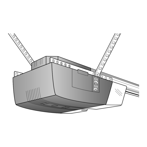
Page 20: Hang The Opener
Installation Step 6 WARNING Hang the Opener The opener could fall and injure someone if it is not properly secured. Fasten the opener securely to structural supports of the garage. Two representative installations are shown. Yours may be different. Hanging brackets should be angled, Figure 1, to provide rigid support. -
Page 21: Install The Door Control And Connect All Wires
Installation Step 7 WARNING WARNING Install the Door Control and Connect all Wiring Do not connect to live electrical wiring. Connect only to 24 Volt low voltage wires. Connection to live wires or higher voltage may cause serious injury from shock, burn or electrocution. Locate the door control within sight of the door at a Children operating or playing with a garage door opener can minimum height of 5 feet where small children cannot... -
Page 22: Electrical Requirements
Installation Step 8 WARNING Electrical Requirements To prevent electrocution or fire, installation and wiring must be in compliance with local electrical and building To reduce the risk of electric shock, your garage door codes. opener has a grounding type plug with a third grounding Do NOT use an extension cord, 2-wire adapter, or change pin. -
Page 23: Install The Lights And Lens
Installation Step 10 Install the Lights and Lens 100 Watt Max. Light Bulb • Install a 100 watt maximum light bulb in each socket. The lights will turn ON and remain lit for approximately 4-1/2 minutes when power is connected. Top Lens Slot Then the lights will turn OFF. -
Page 24: Fasten The Door Bracket (Sectional Door)
Installation Step 12 CAUTION CAUTION Fasten Door Bracket To prevent damage to steel, aluminum, fiberglass or glass panel doors, always reinforce the inside of the door both vertically and horizontally with an angle iron. Follow instructions which apply to your door type as illustrated below or on the following page. -
Page 25: Fasten The Door Bracket (One-Piece Door)
ONE-PIECE DOORS Please read and comply with the warnings and reinforcement instructions on the previous page. They apply to one-piece doors also. • Center the door bracket on the top of the door, in line with the header bracket as shown. Mark either the left and right, or the top and bottom holes. -
Page 26: Connect Door Arm To Trolley (Sectional Door)
Installation Step 13 Connect Door Arm to Trolley Follow instructions which apply to your door type as illustrated below and on page 27. SECTIONAL Doors Only Make sure garage door is fully closed. Pull the manual release handle to disconnect the outer trolley from the inner trolley. -
Page 27: Connect Door Arm To Trolley (One-Piece Door)
All ONE-PIECE Doors Ring Door Assemble the Door Arm: Fastener Bracket Nuts Lock • Fasten the straight and curved door arm sections 5/16"-18 Washers together to the longest possible length (with a 2 or 3 5/16" hole overlap). Clevis Pin Straight 5/16"x1-1/4"... -
Page 28: Adjustment Section: Pages
Adjustment Section: Pages 28 – 30 Adjustment Step 1 WARNING Adjust the UP and DOWN Limits Improper adjustment of the travel limits will interfere with Do not make any limit adjustments until the safety the proper operation of the safety reverse system. The reversing sensors are completely installed. -
Page 29: Force Adjustments
Adjustment Step 2 WARNING Adjust the Force Too much force on the door will interfere with the proper operation of the safety reverse system. The door might Force adjustment controls are located on the right panel not reverse properly when required and could seriously of the opener. -
Page 30: Test The Protector System
Adjustment Step 3 WARNING Test The Protector System ® Without a properly working safety reversing sensor, persons (particularly children) could be seriously injured • Press the remote control push button to open the door. or killed if trapped by a closing garage door. Repeat this •... -
Page 31: Operation Safety Instructions
IMPORTANT SAFETY INSTRUCTIONS WARNING WARNING To reduce the risk of severe injury or death to persons: 1. READ AND FOLLOW ALL INSTRUCTIONS. 2. Do not permit children either to operate or to play with the opener. Keep remote control in a location inaccessible to children. -
Page 32: Operation Of Your Opener
Operation of Your Opener Activate the opener with any of the following: WARNING • The Remote Control Transmitter. Hold push button down until the door starts to move. • The Door Control. Hold push bar down until the door Weak or broken springs could allow an open door to fall starts to move. -
Page 33: Receiver & Remote Control Programming
Receiver and Remote Control Programming WARNING NOTICE: To comply with FCC rules, adjustment or modification of this Children operating or playing with a garage door opener receiver and/or transmitter are prohibited, except for changing the code setting or replacing the transmitter battery. THERE ARE NO OTHER can injure themselves or others. -
Page 34: Having A Problem
Having a Problem? Situation Probable Cause & Solution 1. Does the opener have electric power? Plug a lamp into the outlet. If it doesn't light, check the The opener doesn't fuse box or the circuit breaker. (Some outlets are controlled by a wall switch.) operate from either the door control or 2. -
Page 35: Having A Problem
Having a Problem? (continued) Situation Probable Cause & Solution The door opens but 1. If the opener lights blink, check the safety reversing sensor. See page 22. won't close: 2. If the opener lights do not blink and it is a new installation, check the down force. See Adjustment Step 2, page 29. -
Page 36: Repair Parts, Rail Assembly
Repair Parts Rail Assembly Parts KEY PART NO. NO. DESCRIPTION 41A4796 Hardware bag 41A4795 Hardware bag (includes sprocket coupling) 12B569-1 Left rail bracket 12B569-2 Right rail bracket 1C4827-1 Screw drive rail assembly 12B560 Rail support brace 81C168 Rack 41C4677 Complete trolley assembly 25A18 Sprocket coupling 41A4836 Drive sprocket kit... -
Page 37: Repair Parts, Power Unit
Repair Parts Opener Assembly Parts (Down) crew Drive LIMIT SWITCH ASSY. Brown Contact Wire 2/94 Grey Wire Drive Gear Center Limit (Up) Yellow Contact Contact Wire KEY PART PART DESCRIPTION DESCRIPTION 31D426 Drive shaft cover 41A4843 Interrupter cup 41B4245 Line cord 41A4837 Worm gear and retainer 30B363... -
Page 38: Accessories
Accessories Available For Your Opener Multi-Function Mini Remote 956MM 760CB Outside Keylock: Control: Operates the garage door automatically from outside when With key ring and Velcro fastening remote control is not handy. strip. 950MM 7702CB Outside Quick Release: SECURITY Single-Function Required for a garage with NO Remote Control: access door. -
Page 39: Index
Index Access Door/Outside Quick Release Accessory ....................6, 7, 35, 36 Electrical Safety Warnings ............................2, 22, 31 Garage Door Testing for balance, binding and sticking.........................3, 28, 31 Determining high point of travel: Sectional door..................................12 One-piece door ................................13 Disabling existing locks ..............................3, 11 Force controls Adjustment procedures..............................29 Problems that might require force adjustments......................34, 35... -
Page 40: How To Order Repair Parts
Tucson, Arizona 85745 Toll Free 1-800-528-9096 MASTER MECHANIC/CHAMBERLAIN GARAGE DOOR OPENER ONE-YEAR LIMITED WARRANTY The Chamberlain Group, Inc. (“Seller”) warrants to the first retail purchaser of this product, for the residence in which this product is originally installed, that it will be free from any defect in materials and/or workmanship for a period of one year from the date of purchase.
Need help?
Do you have a question about the Security+ 642-2MM and is the answer not in the manual?
Questions and answers