
Related Manuals for JRRacing XS3


Summary of Contents for JRRacing XS3
- Page 1 xs3_5 10/31/02 3:13 PM Page 1 3-Channel, 6-Model Memory Synthesized FM Computer Racing System...
-
Page 2: Table Of Contents
Up-Timer ....... . . 12 XS3 Data Sheets ......33 Low-Battery . -
Page 3: Xs3 Quick Start Setup
Included in this manual are in-depth instructions detailing all the steps and procedures needed to correctly program each of the XS3’s features. Quick Start covers the basic pro- 1.Determine the frequency band and channels available gramming information necessary to get you to the track marked next to the rotary dial matches the transmitter. - Page 4 10/31/02 3:13 PM Page 4 XS3 Quick Start Continued Throttle Adjustment End-Point (Travel) Adjustment CHANNEL Adjustment Position ST = Steering TH = Throttle 4. Press the Channel key once. “TH” will appear on the E P A AUX = Auxiliary Channel 3 screen.
-
Page 5: Direct Trim Access
xs3_5 10/31/02 3:13 PM Page 5 Direct Trim Access Servo Trim Adjustment T R I M Steering Trim Steering Function 1. With the transmitter power switch on, move the digital steering trim lever in the desired position to Current Value be adjusted. -
Page 6: System Features
(for each servo), • Electronic digital trim levers for throttle and steering instruction manual • Two assignable electronic grip levers • Auxiliary third channel accessible through XS3 Transmitter Grip Lever A Model number • Direct display trim function Encoder 3-channel computer system •... -
Page 7: Control Identification And Location
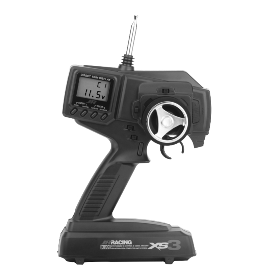
xs3_5 10/31/02 3:13 PM Page 7 Control Identification and Location Antenna Digital Throttle Steering Wheel Trim Lever Dot Matrix Digital Steering Trim Multi-Data Lever LCD Display Power Switch Three-Character Name Input Digital Voltage Reading Scroll Button = Enter Function Channel Button Increase Button = Clear Function Decrease Button... -
Page 8: Rc Safety Precautions
Charger Pigtail For Transmitter it may be reverse polarity and can cause damage to your Black To Positive system. Only use the JR wall charger when the XS3 is equipped with Ni-Cd batteries (JRPB958, available separately). Red To Negative... -
Page 9: Receiver/Servo Connections And Installation
xs3_5 10/31/02 3:13 PM Page 9 Receiver/ Servo Connections and Installation Your RS300 receiver is equipped with Battery Eliminator You may use a separate receiver battery to power the Circuitry (BEC). The receiver gets its power from the receiver (such as for some electric boats or in gas-powered model’s Ni-Cd battery pack, thus saving the weight of an vehicles). -
Page 10: Operating Your Model
xs3_5 10/31/02 3:13 PM Page 10 Receiver/ Servo Connections and Installation Your RS300 needs to be mounted so the receiver is isolated 1. Mount the RS300 receiver with double-sided tape. (Use and floats to avoid damage from shock or vibration. extra layers of double-sided tape, particularly if it is thin, Placement of the RS300’s case should not come in direct until you build up a cushioning pillow layer.) -
Page 11: Servo Layout
xs3_5 10/31/02 3:13 PM Page 11 Servo Layout Servo Arm Retaining Screw Servo Mounting Flange Servo Arm/Horn Servo Output Shaft Rubber Grommets Servo Case Servo Eyelet Servo Mounting Flange Servo Lead with Connector Rubber Grommets Z270/Z590M Servo Note: Rubber grommets and (sometimes) eyelets are used in fuel-powered vehicles. -
Page 12: Display Screens
8. 9V Lithium Battery 10. 2V Your XS3 radio system is equipped with a five-year lithium battery backup system. This system is designed to protect and retain all radio programming in the event that the transmitter batteries drop below the required 9.0 volts, or the transmitter battery case is removed during battery changes. -
Page 13: Accessing The System Mode
xs3_5 10/31/02 3:13 PM Page 13 System Mode Accessing System Mode To enter the System mode, press the Scroll and Channel Note: If you turn the transmitter off and immediate- keys simultaneously while turning on the transmitter power ly enter System mode again, you will be returned to switch. -
Page 14: Model Select
System Mode Model Select Synthesized Channel Select The XS3 has memory for six models. This feature allows One of the XS3 transmitter’s most valued features is its for six different models to be operated with the same trans- ability to synthesize the frequency needed for operation on... -
Page 15: Model Name Entry
Synthesized Channel Select cont. Model Name Entry Accessing the TX Channel Select Function The XS3 allows a three-character name to be input for each of the six models available. The current model with name will then be displayed in the Normal display screen. -
Page 16: Frame Rate Select
xs3_5 10/31/02 3:13 PM Page 16 System Mode Accessing the Frame Rate Function Frame Rate Select The Frame Rate function allows you to select one of two Press and hold the Scroll and Channel keys at the ENTER transmitter frame rates available: Normal “N” - the default SCROLL CHANNEL same time while turning the transmitter power... -
Page 17: Channel 3 Function Select
This feature is designed for use with vehicles such as the The Auxiliary Channel 3 function of the XS3 allows you to Traxxas® T-Maxx. This function is accessible through Grip... -
Page 18: Grip Button C Function Select
Grip Dial B and provide 100% steering rate. This feature is useful if you have The Grip Button C function of the XS3 allows you to select reduced the steering rate to make your vehicle easier to from 3 different functions available. -
Page 19: Data Reset
xs3_5 10/31/02 3:13 PM Page 19 System Mode Copy Model Data Data Reset Copy Model Data function allows you to copy the current The Data Reset function allows you to reset all the pro- model data into the model memory of the blinking model gramming in the selected model (1, 2, 3 4, 5 or 6) to the selected. -
Page 20: Accessing The Function Mode
xs3_5 10/31/02 3:13 PM Page 20 Function Mode Accessing the Function Mode key to select the appropriate channel (if applicable).To To enter the Function mode, turn on the transmitter. Press adjust the values of the function, press the Increase (+) or the Scroll key until a beep is heard. -
Page 21: Throttle Deadband
xs3_5 10/31/02 3:13 PM Page 21 Function Mode Accessing the Throttle Deadband Function Throttle Deadband The throttle deadband feature is used to reduce/eliminate Press the Scroll key until "TDB" appears on the ENTER the dead throttle area that exists at neutral to the starting SCROLL CHANNEL screen. -
Page 22: Exponential
Page 22 Function Mode Accessing the Exponential Function Exponential Function The Exponential feature of the XS3 allows you to alter the Press the Scroll key until "EXP" appears on the ENTER response rate of the steering or throttle control around neu- screen. -
Page 23: End-Point Adjustment
10/31/02 3:13 PM Page 23 Function Mode End-Point Adjustment The End-Point Adjustment feature of the XS3 allows the Backward Throttle (Brake) maximum travel of both the steering, throttle and Auxiliary End-Point Adjustment E P A Channel 3 (optional) servos to be increased or decreased... -
Page 24: Function Mode
xs3_5 10/31/02 3:13 PM Page 24 Function Mode Accessing The End-Point 5. Move the steering wheel, trigger or Grip Button C in the desired direction for adjustment (left/right, forward/ Adjustment Function reverse or brake). Press the Increase or Decrease key to achieve the desired amount of travel. -
Page 25: Programmable Mixing
Page 25 Function Mode Programmable Mixing Accessing The Mixing Adjustment Function The XS3 offers two different mixing adjustments that allows Press the Scroll key until "MIX" appears on the ENTER for mixing one channel to another channel. The mixes SCROLL CHANNEL screen. -
Page 26: Lap-Timer
Page 26 Function Mode Lap-Timer Accessing The Lap-Timer Function The Lap-Timer function of the XS3 allows the recording of individual lap times based on a 999 second up-timer. Press the Scroll key until "LAP" appears on the ENTER Up to 50 laps and times from 3.0 to 99.9 seconds can be... -
Page 27: Sub-Trim
Page 27 Function Mode Accessing the Sub-Trim Function Sub-Trim Press the Scroll key until "TRIM" appears on the The Sub-Trim function of the XS3 is an electronic trimming ENTER SCROLL CHANNEL screen. Press the Channel key to select the desired feature that allows the neutral position of the servo on channel to be adjusted. -
Page 28: Servo Reversing
Servo Reversing 2. Press the Scroll key to access Function Mode. The Servo Reversing feature of the XS3 is a very convenient feature when setting up a new model. The purpose of the 3. Press the Scroll key until “REV . NORM” appears in small servo reversing function is to change the direction of the letters to the right of the screen. -
Page 29: Accessing The Direct Trim Mode
3:13 PM Page 29 Accessing the Direct Trim Mode The Direct Mode function of the XS3 is accessible through To access the Direct Trim Mode function, turn on the trans- the use of the electronic throttle or steering trim levers, as mitter power switch. -
Page 30: Steering Trim
Steering Trim Location Throttle Trim The XS3’s electronic Throttle Trim lever, located to the left Each click will provide 0.3° of trim to the throttle servo with of the steering wheel, allows the center position of the a maximum of 24°... -
Page 31: Grip Lever B: Steering Dual-Rate Trim Adjustment
xs3_5 10/31/02 3:13 PM Page 31 Grip Lever B: Steering Dual-Rate Trim Adjustment The Steering Dual-Rate adjustment, located at Grip Lever B, If the Emergency Steering button function (page 18) is active, allows the Dual-Rate value (maximum servo travel) to be pressing Grip Button C will restore the steering increased or decreased within a range from 100% through dual rate to 100% until the button is released. -
Page 32: Grip Lever A: Brake End-Point Adjustment
When selected, Grip Lever A can be used to access the allows the maximum servo travel on the braking side of the Auxiliary Channel 3 function of the XS3 for use as a fuel throttle trigger to be increased or decreased from 100% to mixture channel. -
Page 33: Xs3 Data Sheets
10/31/02 3:13 PM Page 33 XS3 Data Sheet System Mode MODEL NUMBER CHANNEL # MODEL NAME FRAME RATE AUX FUNCTION O/2P/LN GRIP BUTTON C O/Eb/LA Function Mode STEERING THROTTLE THROTTLE DEADBAND F__________% B__________% EXPONENTIAL __________% F__________% B__________% END-POINT ADJUSTMENT... - Page 34 10/31/02 3:13 PM Page 34 XS3 Data Sheet System Mode MODEL NUMBER CHANNEL # MODEL NAME FRAME RATE AUX FUNCTION O/2P/LN GRIP BUTTON C O/Eb/LA Function Mode STEERING THROTTLE THROTTLE DEADBAND F__________% B__________% EXPONENTIAL __________% F__________% B__________% END-POINT ADJUSTMENT...
- Page 35 10/31/02 3:13 PM Page 35 XS3 Data Sheet System Mode MODEL NUMBER CHANNEL # MODEL NAME FRAME RATE AUX FUNCTION O/2P/LN GRIP BUTTON C O/Eb/LA Function Mode STEERING THROTTLE THROTTLE DEADBAND F__________% B__________% EXPONENTIAL __________% F__________% B__________% END-POINT ADJUSTMENT...
-
Page 36: Frequency Chart
xs3_5 10/31/02 3:13 PM Page 36 Frequency Chart REQUENCY HANNEL REQUENCY HANNEL REQUENCY HANNEL 26.995 ....1 75.530 ....67 75.770 ....79 27.045 ....2 75.550 ....68 75.790 ....80 27.095 ....3 75.570 ....69 75.810 ....81 27.145 ....4 75.590 ....70 75.830 ....82 27.195 ....5 75.610 ....71 75.850 ....83 27.255 ....6... -
Page 37: Warranty And Service Information
xs3_5 10/31/02 3:13 PM Page 37 Warranty and Service Information Note: Be sure to keep your original dated sales Repair Service Directions receipt in a safe place as you will be required to In the event that your JR radio needs service, please follow provide proof of purchase date for the equipment to the instructions listed below. - Page 38 xs3_5 10/31/02 3:13 PM Page 38 944013 580189 JRPM129 ©Copyright 2002 Horizon Hobby, Inc.
Need help?
Do you have a question about the XS3 and is the answer not in the manual?
Questions and answers