Table of Contents
Advertisement
Quick Links
Advertisement
Table of Contents

Related Manuals for Infrasonic Windy6


Summary of Contents for Infrasonic Windy6
- Page 1 - 0 -...
- Page 2 2 digital output audio o interface. This user’s manual is inte ended to give you a step by step guide of the Infrasonic Windy6, to get you us and run the Windy6 ■ Full Features • 6-in/ 6-out FireWire Hig gh-Performance Audio/MIDI interface •...
-
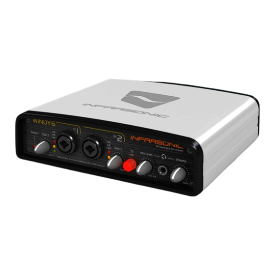
Page 3: Front Panel
2. Description of Windy6 ■ Front Panel 1. Power Indicator LED –Indicates the status of power supply and digital input 2. Input Gain Control – Control input level of each microphone or line input (for both XLS and TRS) 3. SIGNAL and CLIP LED – Indicates the signal level of input 1/2 and clipping 4. -
Page 4: Rear Panel
IEEE1394a(FireWire) cable. – 2 more Windy6s can be linked and used as multi-Device. (It should be required the external power supply) MIDI In/Out Port – Windy6 provides 16 MIDI channe ls I/O 5. S/PDIF 5/6 In/Out Connector –... - Page 5 ● Servo-balanced description 1, Typical Balanced Output Fig1. Balanced connector Balanced signal output is transmitted along with its phase reversed signal (RING) and the output signal level will be amplified by the differential Amp as twice. Fig2. Balanced Signal Output Flow If the balanced output is connected Unbalance jack, the actual inside connection would be TIP &...
- Page 6 2, Servo-Balanced Output To minimize such sound level loss due to the different type of connectors, Servo- Balanced Output controls its gain level in automatically to keep the same level between unbalanced and balanced type signal. Fig 4. Unbalanced Signal Output with Balanced connection When unbalanced signal being input, Servo system is automatically recognized that there’s no signal is feeding from RING and feed amplified signal back to TIP and that makes it flow without any SPL attenuation in any condition.
- Page 7 3. Connections 1. Find the FireWire port on the rear of the Windy 6 2. Connect the included FireWire cable to the FireWire port of the Windy6 3. Find FireWire port on your computer 4. Plug the included the FireWire cable to the FireWire port of your computer.
- Page 8 ■ Connections Descriptions. 1) Microphone • Microphone connects to Input 1/2 on the front panel of Windy6. • Please note that mictophone should be connected by XLR type only. • Select “Inst“ on the control panel as input source. • Adjust gain using Knob on the front panel to control the input level.
-
Page 9: Midi Controller
4) MIDI controller • MIDI OUT in your MIDI controller connects to MIDI IN of Windy6. • If you use an external MIDI instrument, MIDI OUT of Windy6 conects to MIDI IN of your MIDI device. 5) External out board effect •... - Page 10 ● Using multi device • Windy6 supports multi-device function that allows to use 2 more Windy6 at the same time. • No1 Windy6 connects to computer and other 1394 port connects to No2 Windy6 1394 port to use mutiple Windy6 simutaniouly.
-
Page 11: Software Installation
This manual contains a step by step guide for driver software installation to your OS. If you have any difficulties during installation, please contact our technical support department. Install the WINDY6 driver software. Install the provided CD in your CD-Rom drive. Open driver folder and just click setup file and follow the instruction on screen. -
Page 12: Control Panel
5. Control panel The control panel provides you a useful multi channel software mixer with adjustable 6 virtual inputs and outputs. Each of output pair can be routed to any of the Windy6’s four analog or two digital outputs. ■ In/Out Tap 1. - Page 13 Output 5/6(SPDIF) level fader control 3. Device selector – Select the controllable device when using multi device. 4. Windy6 LOGO – Turn on when connecting between computer and wind6 is stabilized. 5. Sample Rate – Select the Sample Rate up to 192kHz.
- Page 14 2. ETC / TOP WINDOWS : This enables the Windy6 panel to be always displayed on the top. RESTORE DEFAULT : Restore the Windy6 to the default factory setting for all configurations. ABOUT : Shows the information of controlpanel This control panel provides you access to assign the Input/ Output level control, cross fader, sync source, configuration, and choose sample rate for your creation.
- Page 15 3. SPDIF monitoring In general, digital output can’t be monitored without additional converter But Windy6 do. Just simply select which IO group you want to hear on the contro l panel (OUT 5/6 = SPDIF output). It is useful function for Infrasonic Blow D series speakers to diagnostic SPDIF works correctly.
- Page 16 ■ Cubase SX and Nuendo 1. After launching Cubase SX, go to Device Device Setup VST Audiobay. Select ‘ASIO2.0-WINDY6’ for the ASIO device. Make sure you need to click Apply button after changing the settings. <Audio Setup in Cubase> - 15 -...
- Page 17 2. After changing the settings, go to Device Device Setup ASIO2.0-WINDY6 If you click the Control Panel button, ‘ASIO-USB Control Panel’ window will pop up. Click the ASIO tab. You can change system performance and application priority. Your system performance affects the latency of the inputs and outputs.
- Page 18 ■ Cakewalk SONAR There are few steps must be done for the SONAR which may supports both WD M and ASIO. After aunhing SONAR, go to option Audio tab. 1. WDM/ KS mode <Audio Setup in Sonar> Change the settings as above in the input/output driver settings. he input and output drivers have to be matched to each other.
- Page 19 2. ASIO mode First, change the driver mode to ASIO in the advanced tab of the audio options as below, then restart SONAR. condly, change the settings as above in the input/output driver settings. <Driver Setup in Sonar> - 18 -...
- Page 20 ■ MAGIX Samplitude After launching SAMPLITUDE, go to Device Device Setup VST Audiobay. Select ‘ASIO2.0-WINDY6’ for the ASIO device. Make s ure you need to click Apply button after chan ging the settings. <Audio Setup in Samplitude> - 19 -...
- Page 21 6. Setting for bundle software Demo versions of NATIVE INSTRUMENTS ABSYNTH 4, MASSIVE and FM are i ncluded on the WINDY6 CD. This software can be operated in stand-alone mode as well as plug-in mode with audio and MIDI sequencers su ch as Cubase, Sonar.
-
Page 22: Block Diagram
7. Block Diagram ■ WINDY6 signal pass - 21 -... -
Page 23: Hardware Specification
8. Hardware Specification ANALOG LINE INPUTS Type Servo-Balanced 1/4” TRS Input Level +-4Bu Nominal (@-11dBFS) , +15dBu max (@0dBFS) +/- 0.05 dB, 20Hz to 20kHz Frequency Response +/- 0.2 dB 20Hz to 80kHz (@ 192kHz sampling rate) Dynamic Range 113dB (1kHz @ -60dBFS, A-weighted) Signal to Noise Ratio 113dB (A-weighted) THD + N... - Page 24 Hi-Z INPUT 1, 2 Type Unbalanced 1/4” TS Input (switched by mechanic relay) Frequency Response +/- 0.2dB, 20Hz to 20kHz Dynamic Range 100dB (1kHz @ -60dBFS, A-weighted, min gain) Signal to Noise Ratio 100dB (A-weighted, min gain) THD+N 0.002% (1kHz @ -3dBFS, min gain) Stereo Crosstalk <-120dB(1kHz @ 0dBFS) Input Impedance...
-
Page 25: End User Warranty
Corr espondence For technical s upport inquiries, co ntact your nearest dealer, distribut or or INFRASONIC directly at: www.infra-sonic.com All features and specif icati ons are subject to change without prior notice. Parts of thi s manual are continually be ing updated.
Need help?
Do you have a question about the Windy6 and is the answer not in the manual?
Questions and answers