Table of Contents

Summary of Contents for Engineered Comfort Fan Coil Controller EZstat
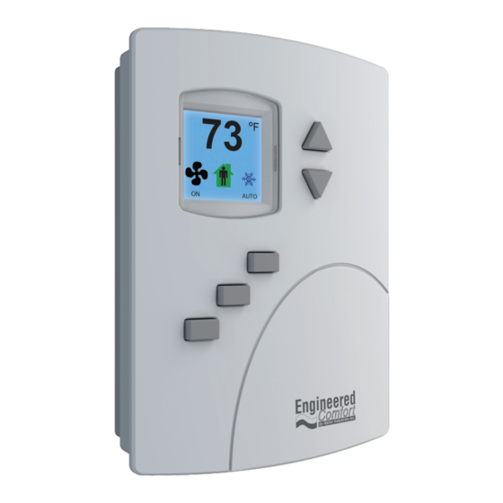
- Page 1 Fan Coil Controller – EZstat www.Engineered-Comfort.com Date: 9-2014 Supersedes: NEW Page 1 of 36 EC-EZstat Engineered Comfort reserves the right to change any information concerning product or specification without notice or obligation.
-
Page 2: Table Of Contents
SYSTEM INTEGRATION ......................30 8.1 BACNET OBJECTS ........................30 8.2 CONNECTING TO MS/TP NETWORK ..................34 Date: 9-2014 Supersedes: NEW EC-EZstat Page 2 of 36 Engineered Comfort reserves the right to change any information concerning product or specification without notice or obligation. -
Page 3: Preface
• Override scheduled occupancy or occupancy based on the schedule in the EZstat • Change the display between Fahrenheit and Celsius Date: 9-2014 Supersedes: NEW Page 3 of 36 EC-EZstat Engineered Comfort reserves the right to change any information concerning product or specification without notice or obligation. -
Page 4: Specifications
Screw terminal block mounted to back‑plate. Wire size 14–22 AWG • Meets or exceeds ANSI/ASHRAE BACnet Standard 135‑2008 for Application Specific Controllers Date: 9-2014 Supersedes: NEW EC-EZstat Page 4 of 36 Engineered Comfort reserves the right to change any information concerning product or specification without notice or obligation. - Page 5 Approximately 6 ounces (170 grams) Case Material Flame retardant plastic Dimensions 1 1/8” (29) 3 1/2” (89) 5 1/8” (130) Date: 9-2014 Supersedes: NEW Page 5 of 36 EC-EZstat Engineered Comfort reserves the right to change any information concerning product or specification without notice or obligation.
-
Page 6: Ezstat Features
Fan Coil Controller – EZstat ● 3.4 EZstat Features Up and Down Buttons Soft Key Soft Key Buttons Date: 9-2014 Supersedes: NEW EC-EZstat Page 6 of 36 Engineered Comfort reserves the right to change any information concerning product or specification without notice or obligation. -
Page 7: Installation
6. Place the top of the sensor over the top of the mounting base and swing it down over the Allen screw bracket. Be careful not to pinch any wiring. Date: 9-2014 Supersedes: NEW Page 7 of 36 EC-EZstat Engineered Comfort reserves the right to change any information concerning product or specification without notice or obligation. -
Page 8: Connecting Inputs
The input includes the internal pull‑up resistor. Fig. 4-2 Wiring for Discharge Air Temperature Sensor Date: 9-2014 Supersedes: NEW EC-EZstat Page 8 of 36 Engineered Comfort reserves the right to change any information concerning product or specification without notice or obligation. -
Page 9: Connecting Outputs
• For a three‑speed, use FAN‑L, FAN‑M, and FAN‑H Fig. 4-4 Connections to a three-speed fan Date: 9-2014 Supersedes: NEW Page 9 of 36 EC-EZstat Engineered Comfort reserves the right to change any information concerning product or specification without notice or obligation. - Page 10 The following diagram shows the connections for a modulating mixing valves. The valve control signal is a 0‑10 V analog output. Fig. 4-6 Connections to modulating heating & cooling valves Date: 9-2014 Supersedes: NEW EC-EZstat Page 10 of 36 Engineered Comfort reserves the right to change any information concerning product or specification without notice or obligation.
-
Page 11: Connecting Power
Remove dust as necessary from the holes in the top and bottom. Clean the display with soft, damp cloth and mild soap. Date: 9-2014 Supersedes: NEW Page 11 of 36 EC-EZstat Engineered Comfort reserves the right to change any information concerning product or specification without notice or obligation. -
Page 12: User Functions
Heating—The system will heat the space until the heating setpoint is reached. The icon is in Heating/Cooling motion when heating is taking place. System is off Heating/Cooling Date: 9-2014 Supersedes: NEW EC-EZstat Page 12 of 36 Engineered Comfort reserves the right to change any information concerning product or specification without notice or obligation. -
Page 13: Entering User Or Admin Password
The display will return to the temperature display COOLING SETPT Cncl Enter Done Date: 9-2014 Supersedes: NEW Page 13 of 36 EC-EZstat Engineered Comfort reserves the right to change any information concerning product or specification without notice or obligation. -
Page 14: Setting The Operating Modes
3. Press the Enter button to save the setting. The display returns to the temperature display. Date: 9-2014 Supersedes: NEW EC-EZstat Page 14 of 36 Engineered Comfort reserves the right to change any information concerning product or specification without notice or obligation. -
Page 15: Commissioning Functions
Users may change the occupied heating and cooling setpoints without accessing the commissioning functions. This procedure is covered in the topic User functions. Date: 9-2014 Supersedes: NEW Page 15 of 36 EC-EZstat Engineered Comfort reserves the right to change any information concerning product or specification without notice or obligation. -
Page 16: Creating And/Or Changing Passwords
7. Repeat steps 5 & 6 for all remaining digits. PASSWORD1: 0 0 0 0 Enter Date: 9-2014 Supersedes: NEW EC-EZstat Page 16 of 36 Engineered Comfort reserves the right to change any information concerning product or specification without notice or obligation. -
Page 17: Setting The Commissioning Setpoints
DIFFERENTIAL Cncl Enter Back the valve according to the demand versus DAT setpoint NOTE Date: 9-2014 Supersedes: NEW Page 17 of 36 EC-EZstat Engineered Comfort reserves the right to change any information concerning product or specification without notice or obligation. -
Page 18: Set Up The Communications
Cncl Enter Done Note: After changing a communication property, the EZstat will reset. NOTE Date: 9-2014 Supersedes: NEW EC-EZstat Page 18 of 36 Engineered Comfort reserves the right to change any information concerning product or specification without notice or obligation. -
Page 19: Set The Time And Date
DST. If DST AUTO is set to TRUE the dates are relative; if set to FALSE the date is a calendar date. Date: 9-2014 Supersedes: NEW Page 19 of 36 EC-EZstat Engineered Comfort reserves the right to change any information concerning product or specification without notice or obligation. -
Page 20: Setting The Occupancy Schedule
• When finished with the schedule push Exit to return to the SCHEDULE menu Date: 9-2014 Supersedes: NEW EC-EZstat Page 20 of 36 Engineered Comfort reserves the right to change any information concerning product or specification without notice or obligation. -
Page 21: Enter The Commissioning Mode
ADVANCED system options Exit Enter Back 2. Press Enter . The SYSTEM menu opens. Date: 9-2014 Supersedes: NEW Page 21 of 36 EC-EZstat Engineered Comfort reserves the right to change any information concerning product or specification without notice or obligation. - Page 22 The Min. and Max. CFMs are also the range at which the ECM operates throughout the sequence when set to auto. NOTE Enter Date: 9-2014 Supersedes: NEW EC-EZstat Page 22 of 36 Engineered Comfort reserves the right to change any information concerning product or specification without notice or obligation.
- Page 23 CFM = 0.0149(Vdc)5 ‑ 0.4423(Vdc)4 + 5.0126(Vdc)3‑ 27.6276(Vdc)2 + 149.7246(Vdc) + 121.2664 Vdc= ‑2.419E‑14(CFM)5 + 7.788E‑11(CFM)4 ‑ 1.007E‑07(CFM)3 + 6.674E‑05(CFM)2 ‑ 9.435E‑03(CFM) + 4.870E‑01 Date: 9-2014 Supersedes: NEW Page 23 of 36 EC-EZstat Engineered Comfort reserves the right to change any information concerning product or specification without notice or obligation.
- Page 24 • MAX VLV HIGH (two pipe only) – Select % valve, opens for high fan speed Enter Date: 9-2014 Supersedes: NEW EC-EZstat Page 24 of 36 Engineered Comfort reserves the right to change any information concerning product or specification without notice or obligation.
-
Page 25: Advanced Options
○ The English version displays temperature in Fahrenheit and uses English values for units of measure (default). Date: 9-2014 Supersedes: NEW Page 25 of 36 EC-EZstat Engineered Comfort reserves the right to change any information concerning product or specification without notice or obligation. - Page 26 • DIM LEVEL—Sets the level of brightness of the display back light Cncl Enter if BACKLIGHT OFF is the selected blanking option. Date: 9-2014 Supersedes: NEW EC-EZstat Page 26 of 36 Engineered Comfort reserves the right to change any information concerning product or specification without notice or obligation.
-
Page 27: Sequences Of Operation
The controller changes to the UNOCCUPIED state only if the internal occupancy schedule is enabled and if the schedule is inactive. Date: 9-2014 Supersedes: NEW Page 27 of 36 EC-EZstat Engineered Comfort reserves the right to change any information concerning product or specification without notice or obligation. -
Page 28: Automatic Cooling And Heating Changeover
The EZstat supports both normal and reverse action valves which can be set from the user interface. Date: 9-2014 Supersedes: NEW EC-EZstat Page 28 of 36 Engineered Comfort reserves the right to change any information concerning product or specification without notice or obligation. -
Page 29: Fan Operation For Fan Coils
Fan minimum is enabled at dead band sequence, and loop percentage not applicable. NOTE Date: 9-2014 Supersedes: NEW Page 29 of 36 EC-EZstat Engineered Comfort reserves the right to change any information concerning product or specification without notice or obligation. -
Page 30: System Integration
Remote Room Sensor KMC10K_Type_II WATER_TEMP Water Temperature KMC10K_Type_III Discharge Air Temp KMC10K_Type_III LOCAL_SENSOR Space Temp KMC10K_Type_II Date: 9-2014 Supersedes: NEW EC-EZstat Page 30 of 36 Engineered Comfort reserves the right to change any information concerning product or specification without notice or obligation. - Page 31 Unknown HIGH Fan High Speed Unknown BINARY_COOLING Cooling Valve Unknown BINARY_HEATING Heating Valve Unknown Date: 9-2014 Supersedes: NEW Page 31 of 36 EC-EZstat Engineered Comfort reserves the right to change any information concerning product or specification without notice or obligation.
- Page 32 Name Description SPACE_TEMP Space Temperature AV19 WATER_TEMP Water Temperature AV20 DISCHARGE_TEMP Discharge Air Temperature Date: 9-2014 Supersedes: NEW EC-EZstat Page 32 of 36 Engineered Comfort reserves the right to change any information concerning product or specification without notice or obligation.
- Page 33 The proportional and integral properties of the cooling and heating loops are available from the user interface. Date: 9-2014 Supersedes: NEW Page 33 of 36 EC-EZstat Engineered Comfort reserves the right to change any information concerning product or specification without notice or obligation.
-
Page 34: Connecting To Ms/Tp Network
• Place a KMD‑5567 surge suppressor in the cable where it exits a building. Illustration 8–1 BACnet MS/TP network wiring Date: 9-2014 Supersedes: NEW EC-EZstat Page 34 of 36 Engineered Comfort reserves the right to change any information concerning product or specification without notice or obligation. - Page 35 Set the end‑of‑line termination to On using the EOL switches. EOL On EOL On Illustration 8-2 Location for end-of-line termination Illustration 8-3 Location of EOL switch Switches Date: 9-2014 Supersedes: NEW Page 35 of 36 EC-EZstat Engineered Comfort reserves the right to change any information concerning product or specification without notice or obligation.
- Page 36 Installation and Operation Manual Fan Coil Controller – EZstat ● THIS PAGE IS LEFT INTENTIONALLY BLANK Date: 9-2014 Supersedes: NEW EC-EZstat Page 36 of 36 Engineered Comfort reserves the right to change any information concerning product or specification without notice or obligation.
Need help?
Do you have a question about the Fan Coil Controller EZstat and is the answer not in the manual?
Questions and answers