Table of Contents
Advertisement
Quick Links
Advertisement
Table of Contents

Subscribe to Our Youtube Channel
Summary of Contents for Klasse KOC-154K
- Page 1 Service Manual KOC-154K Microwave Oven, Convection & Grill SEP. 2008...
-
Page 2: Table Of Contents
PRECAUTIONS TO BE OBSERVED BEFORE AND DURING SERVICING TO AVOID POSSIBLE EXPOSURE TO EXCESSIVE MICROWAVE ENERGY (a) Do not operate or allow the oven to be operated with the door open. (b) Make the following safety checks on all ovens to be serviced before activating the magnetron or other microwave source, and make repairs as necessary: (1) Interlock operation, (2) Proper door closing, (3) Seal and sealing surfaces (arcing, wear, and other damage), (4) Damage to or loosening of hinges and latches, (5) Evidence of dropping or abuse. -
Page 3: Proper Use And Service Precautions
1. PROPER USE AND SERVICE PRECAUTIONS CAUTION This device is to be Serviced only by Properly Qualified Service Personel. Consult the Service Manual for Proper Service Procedures to Assure Continued Safety Operation and for Precautions to be Taken to Avoid Possible Exposure to Excessive Microwave Energy. -
Page 4: Specifications
2. SPECIFICATIONS MODEL KOC-154K9A27 POWER SUPPLY 120V~ 60Hz, SINGLE PHASE WITH EARTHING MICROWAVE 1550W POWER GRILL 1450W CONSUMPTION CONVECTION 1750W COMBINATION 1750W MICROWAVE ENERGY OUTPUT 1000W MICROWAVE FREQUENCY 2450MHz OUTSIDE DIMENSIONS (W X H X D) 582X379.1X518.2mm (22.9x14.9x20.4 in.) CAVITY DIMENSIONS (W X H X D) 390X285.5X383mm (15.4x11.2x15.1 in.) NET WEIGHT Approx. -
Page 5: Feature Diagram
2. FEATURE DIAGRAM 1. DOOR HOOK 8. ROLLER GUIDE When the door is closed, it will automatically lock This must always be used for cooking together with shut. If door is opened while oven is operating, the the turntable tray. magnetron will immediately stop operating. -
Page 6: Installation
4. INSTALLATION 1. Steady, flat location This microwave oven should be set on a steady, flat surface. This microwave oven is designed for counter top use only. 2. Leave space behind and side All air vents should be kept a clearance. If all vents are covered during operation, the oven may overheat and, eventually, cause failure. -
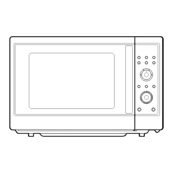
Page 7: Control Panel
5. CONTROL PANEL DISPLAY WINDOW 1. MICROWAVE - indicator, showing microwaving in progress. 2. DEFROST - indicator, showing defrosting in progress. 3. GRILL(upper grill heater) - indicator, showing griling in progress. 4. GRILL(lower grill heater) - indicator, showing griling in progress. 5. -
Page 8: Disassembly And Assembly
6. DISASSEMBLY AND ASSEMBLY - Cautions to be observed when trouble shooting. Unlike many other appliances, the microwave oven is high-voltage, high-current equipment. It is completely safe during normal operation. However, carelessness in servicing the oven can result in an electric shock or possible danger from a short circuit. - Page 9 1. To remove cabinet 1) Remove 5 screws on the cabinet back and side. 2) Push the cabinet backward. 2. To remove door assembly 1) Remove two screws which secure the stopper hinge top. 2) Remove the door assembly from top plate of cavity. 3) Reverse the above for reassembly.
- Page 10 3. To remove door parts. PARTS CODE PARTS NAME DESCRIPTION Q'TY REMARK 3512210300 FRAME DOOR 3515204900 STOPPER HINGE *T AS KOC-1B0K0S 3511714110 DOOR SEAL AS KOC-154K8S 3512302800 GASKET DOOR 3513101800 HOOK 3515101800 SPRING HOOK 3517008920 BARRIER-SCREEN *O GLASS T3.2 TEMPERED 3512607400 HANDLE AS KOC-154K8S...
- Page 11 (1) Remove the gasket door from door plate. (2) Remove two screws from the handle assembly secured to door frame. (3) Remove the handle door and barrier screen outer from door frame. (4) Remove the door frame from door plate. (5) Remove the stopper hinge top from door plate.
- Page 12 5. To remove control panel parts. PARTS CODE PARTS NAME DESCRIPTION Q'TY REMARK 3511617310 DECORATOR C-PANEL 3511617300 DECORATOR C-PANEL STS TO.5 #4 3516735410 CONTROL-PANEL 3516916000 BUTTON FUNCTI0N-A 3516916100 BUTTON FUNCTI0N-B 3516916200 BUTTON FUNCTI0N-C PKBPMSF200 PCB BUTTON MANUAL AS KOC-154K8S 3517401700 COUPLER VPC KNOB 3513411400 KNOB FUNCTION...
- Page 13 6. To remove high voltage capacitor. (1) Remove a screw which secure the grounding ring terminal of the H.V.diode and the capacitor holder. (2) Remove the H.V. diode from the capacitor holder. (3) Reverse the above steps for reassembly. High voltage circuit wiring 7.
- Page 14 8. To remove wind guide assembly. (1) Remove a screw which secure the wind guide assembly. (2) Draw forward the wind guide assembly. (3) Pull the fan from the motor shaft. (4) Remove two screws which secure the motor shaded pole. (5) Remove the motor shaded pole.
- Page 15 10. To remove Guide air assembly parts. PARTS CODE PARTS NAME DESCRIPTION Q'TY REMARK 3512525200 GUIDE AIR PP GP-2300 3513601500 LAMP BL 125V 25W 3515102700 SPRING TERMINAL SUS301 T0.5 3966820200 MOTOR SYNCRO 120V 2W GM-16-12F17 3510609100 BRACKET DAMPER SBHG T0.7 7112401011 SCREW TAPPING T1 TRS 4X10...
- Page 16 11. To remove Top heater assembly parts. REF NO. PART CODE PART NAME DESCRIPTION Q’TY REMARK 7112401011 SCREW TAPPING T1 TRS 4X10 3512523600 GUIDE AIR OUTLET SBHG T0.5 3513304000 INSULATOR HEATER *T SECC TO.5 3511407600 COVER HEATER *T STS430 T0.4 3512806010 REFLECTOR HEATER *T 3512803820...
- Page 17 12. To remove Rear heater assembly parts. REF NO. PART CODE PART NAME DESCRIPTION Q’TY REMARK 3511413500 COVER *B SBHG-3 TO.4 3512806400 HEATER 120V 1400W 7112401011 SCREW TAPPING T1 TRS 4X10 7112401011 SCREW TAPPING T1 TRS 4X10 3513002300 HOLDER HEATER SUS304 T0.5 3512801800 HEATER...
- Page 18 13. To remove Motor synchro. And Under heater assembly parts. CUTTING (6EA) REF NO. PART CODE PART NAME DESCRIPTION Q’TY REMARK 3512806300 HEATER *U 120V 300W 3511407500 COVER HEATER *U STS430 T0.5 3515304000 SUPPORTER HEATER *U STS430 T0.5 7113400814 SCREW TAPPING T1 BIN 4X8 MFNI 7113400814 SCREW TAPPING...
-
Page 19: Interlock Mechanism And Adjustment
7. INTERLOCK MECHANISM AND ADJUSTMENT The door lock mechanism is a device which has been specially designed to completely eliminate microwave radiation when the door is opened during operation, and thus to perfectly prevent the danger resulting from the leakage of microwave. (1) Primary interlock switch When the door is closed, the hook locks the oven door. -
Page 20: Troubleshooting Guide
8. TROUBLESHOOTING GUIDE Following the procedure below to check if the oven is defective or not. 1) Check grounding before trouble checking. 2) Be careful of the high voltage circuit. 3) Discharge the high voltage capacitor. 4) When checking the continuity of the switches, fuse or high voltage tranformer, disconnect one load wire from these parts and check continuity with the AC plug removed. - Page 21 CONDITION CHECK RESULT CAUSE REMEDY Defective Outlet has Check continuity of Replace continuity magnetron. proper magnetron voltage fuse does not blow? Defective line Check continuity of noise filter Replace continuity filter board board Open power Check continuity of Replace continuity power supply cord supply cord Defective touch...
- Page 22 TROUBLE 3) No microwave oscillation even though fan motor rotates. CONDITION CHECK RESULT CAUSE REMEDY Check continuity of Replace Defective continuity high voltage fuse microwave high voltage oscillation fuse No microwave oscillation Continuity Check continuity of Defective high voltage capacitor terminals high voltage with wires removed transformer...
- Page 23 (TROUBLE 4) Grill heater (upper heater) is not heated; food will not become hot. CONDITION CHECK RESULT CAUSE REMEDY Malfunction of Adjust or Check continuity of Grill heater is primary Interlock replace continuity primary interlock switch not heated. switch Adjust or Malfunction of Check continuity of replace...
- Page 24 (TROUBLE 6) Lower heater is not heated; food will not become hot. CONDITION CHECK RESULT CAUSE REMEDY Malfunction of Adjust or Check continuity of Lower heater primary Interlock Replace continuity Is not heated Primary interlock switch switch Adjust or Check continuity of Malfunction of replace secondary interlock...
- Page 25 (TROUBLE 8) When “ERROR 2 ERROR 3” come on display. CAUSE CONDITION CHECK RESULT REMEDY “ERROR 2 & 0Ω or infinite Replace Replace Check continuity of thermistor ERROR 3” (resistance of thermistor) come on display Approx 200k~300kΩ (room temperature) Defective Replace Check continuity of heater continuty...
-
Page 26: Mesurement And Test
9. MEASUREMENT AND TEST 9-1. MEASUREMENT OF THE MICROWAVE POWER OUTPUT Microwave output power can be checked by indirectly measuring the temperature rise of a certain amount of water exposed to the microwave as directed below. PROCEDURE 1. Microwave power output measurement is made with the microwave oven supplied at rated voltage and operated at its maximum microwave power setting with a load of 1000 ±... -
Page 27: Microwave Radiation Test
9-2. MICROWAVE RADIATION TEST WARNING 1. Make sure to check the microwave leakage before and after repair of adjustment. 2. Always start measuring of an unknown field to assure safety for operating personnel from microwave energy. 3. Do not place your hands into any suspected microwave radiation field unless the safe density level is known. 4. -
Page 28: Component Test Procedure
9-3. COMPONENT TEST PROCEDURE • High voltage is present at the high voltage terminal of the high voltage transformer during any cooking cycle. • It is neither necessary nor advisable to attempt measurement of the high voltage. • Before touching any oven components or wiring, always unplug the oven from its power source and discharge the capacitor. -
Page 29: Component Action
9-4. COMPONENT ACTION MAGNE- UPPER LOWER REAR CONVEC- COOKING MODE TRON ELEMENT ELEMENT ELEMENT TION FAN GRILL-1 GRILL-2 COMBI-1 MANUAL COMBI-2 MODE COMBI-3 COMBI-4 COMBI-5 CONVECTION40 CONVECTION100~220 FRESH PIZZA FROZEN PIZZA TOUCH FRESH GRATIN (CRUSTY/ FROZEN GRATIN CAKE) CAKE BREAD ROAST BEEF ROAST CHICKEN AUTO... -
Page 30: Wiring Diagram
10. WIRING DIAGRAM... -
Page 31: Exploded View And Parts List
11. EXPLODED VIEW AND PARTS LIST TOTAL ASSEMBLY * From A00 to G00 and P00, refer to 6. Disassembly and assembly. - Page 32 Caution : In this Manual, some parts can be changed for improving, their performance without notice in the parts list. So, if you need the latest parts information, please refer to PPL(Parts Price List) in Service Information Center (http://svc.dwe.co.kr). PARTS CODE PARTS NAME DESCRIPTION Q'TY...
- Page 33 Caution : In this Manual, some parts can be changed for improving, their performance without notice in the parts list. So, if you need the latest parts information, please refer to PPL(Parts Price List) in Service Information Center (http://svc.dwe.co.kr). PARTS CODE PARTS NAME DESCRIPTION Q'TY...
-
Page 34: Printed Circuit Board
12. PRINTED CIRCUIT BOARD CIRCUIT CHECK PROCEDURE 1. Low voltage transformer check The low voltage transformer is located on the P.C.B. Measuring condition: Input voltage: 120V / Frequency: 60Hz Terminal Voltage(load) Voltage(no load) AC 17.0 V AC 19.9 V AC 1.3 V AC 1.6 V 9-10 AC 1.3 V... - Page 35 3. Case of no microwave oscillation 1) When touching M/W button, oven lamp turns on and Fan motor and turntable rotate, and cook indicator in display comes on. *Cause: RELAY 1 does not operate. - Check method STATE POINT A POINT B RELAY 1 ON +5V DC...
- Page 36 4. Case of no heating of upper grill When touching GRILL1 & COMBI button, oven lamp turns on and Fan motor and turntable motor rotate and cook indicator in the display comes on. *Cause: RELAY 4 does not operate. STATE POINT A POINT B RELAY 4 ON...
- Page 37 7. Case of no stopping of the count down timer When the door is opened during operation, the count down timer does not stop. - Check method POINT STATE DOOR OPEN OPEN +5V DC DOOR CLOSED CLOSE CHECK NO METHOD REMEDY Check the stage(ON,OFF) of the door open Replace door open monitor swith.
-
Page 38: Circuit Diagram
13. P.C.B. CIRCUIT DIAGRAM... - Page 39 NAME LOCATION PART CODE SPECIFICATION Q'TY REMARK BUZZER 3515600100 BM-20K C CERA C1~4,7~13 CCZF1H104Z 50V HIKF 0.1uF Z C CERA C5,6 CCZB1H102K 50V B 1000pF K C ELECTRO CEXE1H100A 50V RS 10uF (5X11) TP C ELECTRO EC2,EC3 CEXF1V221V 35V RSS 220uF (10X12.5) TP C ELECTRO CEXF1V102V 35V RSS 1000uF (13X25) TP...
- Page 40 NAME LOCATION PART CODE SPECIFICATION Q'TY REMARK 42 SW RELAY RY1,2 5SC0101122 G5G-1A 1C 1P DC24V 43 SW RELAY RY3~5 5SC0101124 G5G-1A-DT 1C 1P DC24V 44 SW RELAY RY6~9 5SC0101129 CS11-24SH 1C 1P 45 TR Q5~8,10~14,17 TZRC106M-- KRC-106M (AUTO) 46 TR Q1,4 TZTA1266Y- KTA-1266Y (AUTO) (1015Y)
- Page 41 DAEWOO ELECTRONICS CORP. 686, AHYEON-DONG MAPO-GU SEOUL, KOREA C.P.O. BOX 8003 SEOUL, KOREA TELEX: DWELEC K28177-8 CABLE: “DAEWOOELEC” S/M NO. : PRINTED DATE: Sep. 2008...
Need help?
Do you have a question about the KOC-154K and is the answer not in the manual?
Questions and answers