Table of Contents
Advertisement
Quick Links
Advertisement
Table of Contents

Related Manuals for Opus AMR650 V2.0


Summary of Contents for Opus AMR650 V2.0
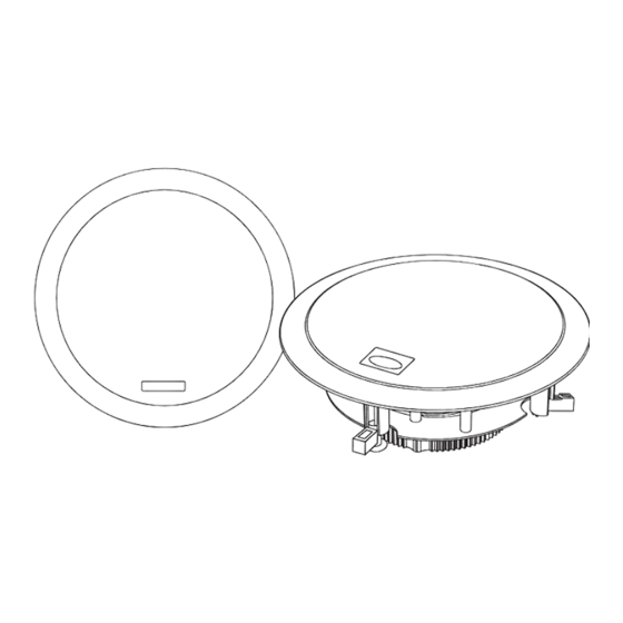
- Page 1 AMR650 V2.0 A-BUS Active Ceiling Speakers Installation Guide...
-
Page 2: Table Of Contents
1 x painting mask Care and maintenance..............5 If any of the above items are missing or appear damaged, contact your Opus dealer immediately. Do not throw the away the AMR650-A rear connections............6 packaging in case you need to return your AMR650 V2.5. -
Page 3: Introduction
It uses the Octopus MCU300 as the hub or connects to an Opus sub-zone output etc. The AMR650 V2.0 consists of one active speaker with a stereo AMR650-A power amplifier and other electronics built-in (AMR650-A ); and one passive speaker (AMR650-P). -
Page 4: Installation Notes
Min 80mm When placing the AMR650 V2.0 speakers, thought should be given Min 10-30mm to positions which give the best desired sound coverage throughout a room, while not interfering with existing or planned light fittings or joists. -
Page 5: Painting The Amr650 V2.0
PAINTING THE AMR650 V2.0 1. Remove the grille by inserting a small hook or similar small implement into one of the grille openings, then pulling on the grille. For the AMR650-A, carefully disconnect the IR connector lead before proceeding. 2. Fit the clear plastic painting mask provided when painting the speaker surround to avoid getting paint getting on the speaker cone. -
Page 6: Amr650-A Rear Connections
6 – Stereo/Mono jumper (CN14) 7 – Cat-5e connection to passive speaker 8 – Speaker cable connection to passive speaker 9 – 123 jumper (no current function) 10 – Opus/A-BUS mode jumper 11 – Local jumper 12 – Fader jumper... -
Page 7: Amr650-A Jumper Settings
A-BUS mode For use with an Octopus MCU300 A-BUS hub the jumper MUST be in the OPUS position. For use with standard A-BUS hubs and amplifiers from other manufacturers (or as a sub-zone to a MCU500 based system) the jumper MUST be in the A-BUS position. -
Page 8: Connecting The Amr650 V2.0
CONNECTING THE AMR650 V2.0 EIA / TIA 568A wiring standard 1. Using a single Cat5e cable, connect the AMR650-A to the Cat5e cable terminated at AMR650 (view from contact end): MCU300 via an RJ45 plug at the Master Control Unit, and the 8- V2.0 8-way punch down connector:... -
Page 9: Mounting The Amr650 V2.0
MOUNTING THE AMR650 V2.0 1. Before mounting, ensure that the four fixing screws are slackened off so that the red mounting dog-legs can move freely. 2. Move each red dog-leg foot to the LEFT into it’s holding slot, and then insert the speaker into the mounting hole. -
Page 10: Advanced Features
It is possible to install a piece of source equipment to be used local The default mode for the AMR650-A is stereo, but there are two optional to the room that contains the AMR650 V2.0. This might be a games mono modes: machine or CD player in the bedroom, for example. - Page 11 The AMR650 is powered directly from the MCU300 via the Cat5 cable. If your installation has very long cable runs from the MCU300 to the AMR650 V2.0 (greater than 30M) the AMR650 V2.0 must be locally powered instead. This simply involves plugging an Opus...
-
Page 12: Operating The Amr650 V2.0
OPERATING THE AMR650 V2.0 The AMR650 V2.0 can be operated entirely via an Octopus SRC300 (pictured) or LRC300 remote handset: 1. Source select Selects source to be listened to. 2. EXT/CCTV Selects CCTV source on the VSU300 if fitted. 3. All off Switches the whole system to Standby. -
Page 13: Sound Adjustment Functions
Volume buttons speakers, and any extra One bleep will sound times: four bleeps will sound equipment connected to the AMR650 V2.0 pre-amp output (Up = towards main, Treble Down = towards pre-amp) During sound adjustment tones are generated to indicate... -
Page 14: Technical Specifications
TECHNICAL SPECIFICATIONS Frequency response 60Hz–20kHz (+/- 2dB) This guide is designed to make using the AMR650 V2.0 as easy as possible. Information in this document has been carefully checked <0.25% @ 5W, 1kHz for accuracy; however, no guarantee is given to the correctness of the contents. -
Page 15: Limited Warranty
LIMITED WARRANTY Opus Technologies warrants this product to be free from defects in This Warranty does not cover cosmetic damage or damage due to materials and workmanship (subject to the terms set forth below). acts of God, accident, misuse, abuse, negligence, commercial use, Opus Technologies will repair or replace (at Opus Technologies’... - Page 16 Opus is committed to providing the highest levels of service and support. For full details of this product visit the Opus website: www.opus-technologies.co.uk Part No. AP18922/1...
Need help?
Do you have a question about the AMR650 V2.0 and is the answer not in the manual?
Questions and answers