
Related Manuals for A-C Fire Pump 8200 Series

Summary of Contents for A-C Fire Pump 8200 Series
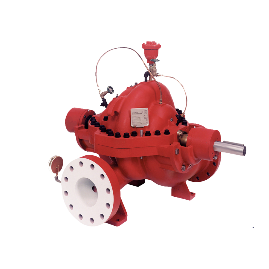
- Page 1 Instruction Manual AC2675 REVISION A 8200 Series Base Mounted Centrifugal Fire Pumps Installation, Operation and Service Instructions INSTALLER: PLEASE LEAVE THIS MANUAL FOR THE OWNER’S USE.
-
Page 2: Table Of Contents
DISMANTLING (PUMP WITH PACKING) .. 24 ASSEMBLY (PUMP WITH PACKING) ... 27 APPENDIX “A” ENGINEERING DATA ... 30 APPENDIX “B” ... 31 EXPLODED VIEW – 8200 SERIES FIRE PUMP ... 31 REPLACEMENT PARTS LIST ... 32 INSTRUCTIONS FOR ORDERING PARTS33 APPENDIX “C”... -
Page 3: Description
DESCRIPTION The 8200 Series Centrifugal Fire Pumps are framed mounted pumps which feature – high efficiency, rugged construction, compact design, foot mounted volute and regreasable bearings. These features, along with the horizontal split case, make installation, operation and service easy to perform. -
Page 4: Safety Instructions
IS INVOLVED! FAILURE TO FOLLOW THE INSTRUCTIONS MAY RESULT IN A SAFETY HAZARD. Your 8200 Series Centrifugal Fire Pump should have the following safety instruction decals displayed. If the decals are missing or illegible contact your local ITT A-C Fire Pump Systems representative for a replacement. -
Page 5: Additional Safety Requirements
ADDITIONAL SAFETY REQUIREMENTS: ELECTRICAL SAFETY: WARNING: Electrical Shock Hazard Electrical connections to be made by a qualified electrician in accordance with all applicable codes, ordinances, and good practices. Failure to follow these instructions could result in serious personal injury or death, and property damage. -
Page 6: Installation
PUMP LOCATION Locate the pump so there is sufficient room for inspection, maintenance and service. If the use of a hoist or tackle is needed, allow ample head room. WARNING: Falling Objects Hazard Eyebolts or lifting lugs, if provided, are for lifting only the components to which they are attached. -
Page 7: Temporary Storage
installation. ITT AC Fire Pump Systems has determined that proper and correct alignment can only be made by accepted erection practices. Refer to the following paragraphs on “Foundation,” “Base Plate Setting,” “Grouting Procedure,” “Alignment Procedure” and “Doweling.” TEMPORARY STORAGE If the pump is not to be installed and operated soon after arrival, store it in a clean, dry place having slow, moderate changes in ambient temperature. -
Page 8: Base Plate Setting (Before Piping)
BASE PLATE SETTING (BEFORE PIPING) NOTE: This procedure assumes that a concrete foundation has been prepared with anchor or hold down bolts extending up ready to receive unit. It must be understood that pump and motor have been mounted and rough aligned at the factory. -
Page 9: Ansi/Osha Coupler Guard Removal/Installation
vibration, and bearing loads that result in premature bearing failure and ultimate seizing of the pump. Misalignment can be angular, parallel, or a combination of these, and in the horizontal and vertical planes. Final alignment should be made by moving and shimming the motor on the base plate, until the coupling hubs are within the recommended tolerances measured in total run-out. - Page 10 ANSI/OSHA Coupling Guard Exploded View For Typical 8200 Series Fire Pump Installation OUTER GUARD LOCATE SUPPORT ARM BETWEEN OUTER GUARD ENDS. ALIGN THE ARM WITH HOLES IN THE OUTER GUARD AND HOLES IN THE SADDLE BRACKET. LOCKWASHER MOTOR SADDLE BRACKET ATTACH TO MOTOR SADDLE Method 1 –...
-
Page 11: Angular Alignment
Method 2 – For Orange Hytrel Insert, 3500 RPM Operation, or All Other Coupler Types (See Figure 7B) a. Make sure each hub is secured to its respective shaft and that all connecting and/or spacing elements are removed at this time. b. - Page 12 and properly aligned, so that no strain is transmitted to the pump when the flange bolts are tightened. Use pipe hangers or other supports at necessary intervals to provide support. When expansion joints are used in the piping system, they must be installed beyond the piping supports closest to the pump.
- Page 13 Suction piping should be short in length, as direct as possible, and never smaller in diameter than the pump suction opening. A minimum of ten (10) pipe diameters between any elbow or tee and the pump should be allowed. If a long suction pipe is required, it should be one or two sizes larger than the suction opening, depending on its length.
-
Page 14: Stuffing Box Lubrication
Pressure Gauges Properly sized pressure gauges should be installed in both the suction and discharge nozzles in the gauge taps provided. The gauges will enable the operator to easily observe the operation of the pump, and also determine if the pump is operating in conformance with the performance curve. - Page 15 box. Excess pressure from an external source can be very destructive to packing. More pressure is required, however, for abrasive slurries than for clear liquids. Examination of the leakage will indicate whether to increase or decrease external pressure. If slurry is present in the leakage, increase the pressure until only clear liquid drips from the box.
-
Page 16: Operation
WARNING: Unexpected Startup Hazard Disconnect and lockout power before servicing. Failure to follow these instructions could result in serious personal injury or death, or property damage. WARNING: Electrical Shock Hazard Electrical connections to be made by a qualified electrician in accordance with all applicable codes, ordinances, and good practices. -
Page 17: Freezing Protection
b. Check and record pressure gauge readings for future reference. c. Check and record voltage, amperage per phase, and kw if an indicating wattmeter is available. d. Check bearings for lubrication and temperature. Normal temperature is 180° maximum. e. Make all pump output adjustments with the discharge line. -
Page 18: Bearing Lubrication - Grease
Bearings are a primary concern on pumping units. First, dismantle the bearings; clean and inspect them for any rusted or badly worn surfaces. If bearings are free from rust and wear, reassemble and relubricate them with one of the recommended pump lubricants. Depending on the length of time the pump has remained in the flooded area, it is unlikely that bearing replacement is necessary;... -
Page 19: Every Month
MAINTENANCE TIME TABLE Check bearing temperature with a thermometer, not by hand. If bearings are EVERY MONTH running hot (over 180°F), it may be the result of too much lubricant. If changing the lubricant does not correct the condition, disassembly and inspect the bearings. Lip seals bearing on the shaft may also cause the housing to run hot. -
Page 20: Trouble Shooting
Between regular maintenance inspections, be alert for signs of motor or pump trouble. Common symptoms are listed below. Correct any trouble immediately and AVOID COSTLY REPAIR AND SHUTDOWN. CAUSES 1. Lack of prime. 2. Loss of prime. 3. Suction lift too high (a negative suction gauge reading). - Page 21 TROUBLE SHOOTING (CONT.) CAUSES 16. Impeller partially plugged. 17. Cavitation; insufficient NPSHA (Net Positive Suction Head Available). 18. Defective impeller. 19. Foot valve too small or partially obstructed. 20. Suction inlet not immersed deep enough. 21. Wrong direction of rotation. 22.
- Page 22 TROUBLE SHOOTING (CONT.) CAUSES Pump Operates For Short Time, Then Stops 30. Insufficient NPSHA. 31. System head too high. 32. Head lower than rating; thereby pumping too much liquid. 33. Cavitation 34. Mechanical defects. 35. Suction inlet not immersed. 36. Liquid heavier (in either viscosity or specific gravity) than allowed for.
-
Page 23: Changing Rotation
Do not operate pump without all guards in place. Failure to follow these instructions could result in serious personal injury or death and property damage. 8200 Series centrifugal pumps can be operated clockwise or counterclockwise when viewed from the coupling end of the pump. If you wish to reverse the suction and discharge nozzles;... -
Page 24: Service Instructions
DISASSEMBLY AND REASSEMBLY PROCEDURES The procedures outlined in this section cover the dismantling and reassembly of the 8200 Series Centrifugal Fire Pumps. When working on the pump, use accepted mechanical practices to avoid unnecessary damage to parts. Check clearances and conditions of parts when pump is dismantled and replace if necessary. - Page 25 12. Remove casing rings (3-003-9) from impeller (4-002-0). 13. Remove set screw (3-902-9) from shaft nuts. Remove shaft nuts (3-015-9), O-rings (3-914-9), sleeves (3-009-9), interstage bushing (3-231-0), and impellers (4-002-0). NOTE: Apply heat uniformly to the shaft sleeve to loosen the sealant between the shaft and sleeve.
- Page 26 2ND STAGE IMPELLER FIGURE 11 – ASSEMBLY SECTION: PUMP WITH PACKING CLOCKWISE ROTATION 1ST STAGE IMPELLER FIGURE 12 – ASSEMBLY SECTION: PUMP WITH PACKING COUNTER-CLOCKWISE ROTATION Dimension “A” = 12.06” Dimension “A” = 12.06” 1ST STAGE IMPELLER 2ND STAGE IMPELLER...
-
Page 27: Assembly (Pump With Packing)
ASSEMBLY (PUMP WITH PACKING) All bearings, O-rings, seals, gaskets, impeller rings, and casing wear rings should be replaced with new parts during assembly. All reusable parts should be cleaned of all foreign matter before reassembling. The main casing joint gasket can be made using the upper or lower half as a template. - Page 28 race contacting, as shown on assembly section). a) Remove the preservative from the outside diameter and faces of the bearings. Heat both bearings to 200°F at the same time. Place the first bearing on the shaft. Very quickly place the second bearing on the shaft. When installing the second bearing, push against the inner race to remove all clearance between the inner races...
- Page 29 24. Assemble rotating element in lower half casing. Correctly locate casing ring pins, stuff box bushing pins, and interstage diaphragm pins in casing main joint slots. Sliding the inboard bearing housing towards the coupling slightly will ease assembly. 25. Bolt outboard bearing housing in place. Be sure that both housings are seated properly in lower half casing.
-
Page 30: Appendix "A" Engineering Data
APPENDIX “A” ENGINEERING DATA Pump Size Number of Stages Approval Flow Rate (GPM) Flange Rating ASA Suction Standard Discharge Casing Material Max. Working Pressure (PSIG) Max. Suction Pressure (PSIG) Max. Hydrostatic Pressure (PSIG) Standard Hydrostatic Test Pressure (PSIG) Casing Wall Thickness Bore Depth Packing: No. -
Page 31: Appendix "B
APPENDIX “B” EXPLODED VIEW – 8200 SERIES FIRE PUMP CLOCKWISE ROTATION... -
Page 32: Replacement Parts List
REPLACEMENT PARTS LIST Part Number 1-952-0 1-952-0 0-910-9 1-013-9 1-014-9 1-901-9 1-909-9 1-924-9 2-001-7 2-001-8 2-123-5 2-123-5 2-904-1 1-439-0 3-003-9 3-007-0 3-009-9 3-015-9 5-018-0 3-025-3 3-026-3 3-026-4 5-050-4 5-421-4 3-169-9 3-177-9 3-516-4 3-514-4 3-902-9 5-904-9 3-911-1 3-911-2 3-914-9 6-914-9 6-008-0 3-034-0 3-231-0 3-914-7... -
Page 33: Instructions For Ordering Parts33
INSTRUCTIONS FOR ORDERING PARTS When ordering parts for 8200 Series Fire Pumps, be sure to furnish the following information to the ITT A-C Fire Pump Systems stocking distributor in your area: – Serial Number – Pump Size & Type –... -
Page 34: Appendix "C" Field Test Report
APPENDIX “C” FIELD TEST REPORT... -
Page 35: Useful Formulas
APPENDIX “C” FIELD TEST REPORT USEFUL FORMULAS Pressure (psig.) 2.31 1) Head (ft.) = S.G. 2) TDH (ft.) = Total Dynamic Head (ft.) = (Disch. pressure gauge reading - Suct. pressure gauge reading) + 3) PUMP INPUT HP (BHP) - calculated: Single Phase Motor Amps x Volts... - Page 36 © COPYRIGHT 2005 BY ITT INDUSTRIES, INC. PRINTED IN U.S.A. 11-05 A-C Fire Pump 8200 N. Austin Avenue Morton Grove, IL 60053 Phone: (847) 966-3700 Fax: (847) 966-1914 www.acfirepump.com In Canada Fluid Products Canada 55 Royal Road Guelph, Ontario, N1H 1T1, Canada Phone: (519) 821-1900 Fax (519) 821-2569...
Need help?
Do you have a question about the 8200 Series and is the answer not in the manual?
Questions and answers