Table of Contents
Advertisement
UHF FM TRANSCEIVER
TK-372G
SERVICE MANUAL
GENERAL ...................................................................... 2
SYSTEM SET-UP .......................................................... 2
OPERATING FEATURES .............................................. 3
REALIGNMENT ............................................................. 7
DISASSEMBLY FOR REPAIR ..................................... 15
CIRCUIT DESCRIPTION ............................................. 16
SEMICONDUCTOR DATA .......................................... 20
DESCRIPTION OF COMPONENTS ............................ 22
PARTS LIST ................................................................. 23
EXPLODED VIEW ....................................................... 31
PACKING ..................................................................... 32
Antenna
(KRA-15: Option)
Knob (PTT)
(K29-5334-13)
Knob (Side1)
(K29-5333-13)
CONTENTS
©
2000-11 PRINTED IN JAPAN
B51-8561-00(S) 790
Knob (ENC)
(K29-5331-03)
Knob (VOL)
(K29-5332-03)
Cabinet assy
(A02-3568-23)
Key top
(K29-9043-02)
ADJUSTMENT ............................................................. 33
DISPLAY UNIT (X54-3250-10) ............................... 45
TX-RX UNIT (X57-588X-XX) .................................. 47
SCHEMATIC DIAGRAM .............................................. 53
BLOCK DIAGRAM ....................................................... 57
LEVEL DIAGRAM ........................................................ 59
KNB-14/KNB-15A (Ni-Cd BATTERY) .......................... 60
OPTIONS ..................................................................... 61
SPECIFICATIONS ................................... BACK COVER
Advertisement
Table of Contents

Related Manuals for Kenwood TK-372G


Summary of Contents for Kenwood TK-372G
-
Page 1: Table Of Contents
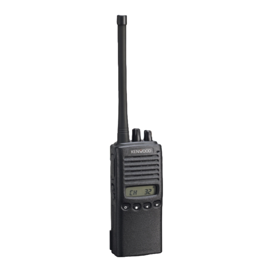
UHF FM TRANSCEIVER TK-372G SERVICE MANUAL © 2000-11 PRINTED IN JAPAN B51-8561-00(S) 790 Antenna (KRA-15: Option) Knob (ENC) (K29-5331-03) Knob (VOL) (K29-5332-03) Cabinet assy (A02-3568-23) Knob (PTT) (K29-5334-13) Knob (Side1) (K29-5333-13) Key top (K29-9043-02) CONTENTS GENERAL ..............2 ADJUSTMENT ............. 33 SYSTEM SET-UP ............ -
Page 2: General
X57-5880-13 403~430MHz SYSTEM SET-UP Merchandise received Frequency range (MHz) RF power Type TX/RX 450~470 4.0W TK-372G K License and frequency allocated by FCC TX/RX 470~490 4.0W TK-372G K2 4.0W TK-372G K3 TX/RX 490~512 Choose the type of transceiver TX/RX 403~430 4.0W... -
Page 3: Operating Features
TK-372G OPERATING FEATURES o o o o o Display 1. Operation Features Note: The PF keys are programmed with default functions: • Side 1 key: Lamp Antenna • Side 2 key: Monitor A w w w w w e e e e e q q q q q °... - Page 4 TK-372G OPERATING FEATURES The "Add" channel is contained in the scan sequence, the 4) Home Channel "Delete" channel is not contained. In the scan mode, this key Press this key once, the channel switches to the pre- switches the channel between delete or add, temporarily.
- Page 5 TK-372G OPERATING FEATURES channel to answer to the call however revert channel is set Multiple Group Scan to priority channel. You can scan all valid (ADD) channels in all valid (ADD) After resume time, scan re-starts and the transmission groups.
- Page 6 TK-372G OPERATING FEATURES The transceiver is capable of having ID. The format is DTMF. 6. Option Signalling (DTMF/2 tone) The timing that the transceiver sends the ID is Built-in DTMF decoder is available for option signalling. programmable. Built-in 2-Tone decoder is available for option signalling.
-
Page 7: Realignment
TK-372G OPERATING FEATURES/ REALIGNMENT REALIGNMENT 7. Audible user feedback tones The transceiver outputs various combinations of tones to 1. Modes notify the user of the transceiver operating state. The main tones are listed below User mode The high tone is 1477Hz, the mid tone is 941Hz, and the low tone is 770Hz. - Page 8 4. Set the firmware to be updated by File select (=F1). the future. (For details on how to obtain the firmware, contact 5. Hold down the [Side1] and [Side2] switches on the TK-372G, Customer Service.) and press the power switch.
-
Page 9: Self Programming Mode
Self Programming is disabled if "a Trunking Board is the receive radio is the slave). installed in this Radio" is selected in FPU. 1. Turn the master TK-372G power ON with the [Side1]+[3] key held down. The TK-372G displays " CLONE ". - Page 10 1-128 _1-_1._ We recomend up to 32 CH Both P.ID_3 Channel _1-128._ for TK-372G. 16 Begin of 000- _BOT_ID_ Not valid if Dial ID =Disable and 1 RX frequency Step 2.5kHz-1MHz STP_250 Display when an item is selected TX ID 9999999999999999 PTT ID=OFF, or EOT is set.
- Page 11 TK-372G REALIGNMENT 8-3. Function Setting Mode Flow Chart Channel Setting Mode This is a mode for using the panel keys to make function settings without using the FPU, that operate on all channels. Self programming mode [Side2] Pressing the [Side1] when "SELF" is displayed, sets the...
- Page 12 TK-372G REALIGNMENT No. Function Choices Display Remarks No. Function Choices Display Remarks 2 [Side2] RF Power Low MON_21 5 [2] Channel Up KEY3_9 Scan MON_22 Keylock KEY3_10 Scan DEL/ADD MON_23 Lamp KEY3_11 Operator MON_27 2-Tone Encode KEY3_16 Selectable Tone Select °...
- Page 13 Tuning MODE Disable PTM_DIS Fixed PRI_FIX_ Selected PRI_SEL_ *1. This function is not available on TK-372G. 20 Lock Back 0.5-5.0/0.05 LBA_500 Default:500ms Cannot be Time A set when Priority = none. 8-4. Memory Reset Mode 21 Lock Back 0.5-5.0/0.05 LBB_2000 Default:2000ms Cannot...
- Page 14 TK-372G REALIGNMENT Flow Chart Function Setting Mode [Side1] [Side1] Group code Self programming mode Squelch level [Side1] [2]/[3] [2]/[3] [Side1] [Side1] [Side1] Auto reset time Function set mode Priority [2]/[3] [2]/[3] [Side1] [Side1] [Side1] [Side1] key function Look back time A...
-
Page 15: Disassembly For Repair
TK-372G DISASSEMBLY FOR REPAIR Separating the case assembly from the chassis. Separating the chassis from the unit. 1. Remove the two knobs and three round units 1. Remove the three screws 2. Remove the two screws Lift the unit (X54), and rise up the connecter lever in the 3. -
Page 16: Circuit Description
TK-372G CIRCUIT DESCRIPTION 3) IF Amplifier circuit 1. Frequency configuration The first IF signal is passed through a four-pole monolithic The receiver utilizes double conversion. The first IF is 49.95 crystal filter (XF1) to remove the adjacent channel signal. MHz and the second IF is 450 kHz. The first local oscillator The filtered first IF signal is amplified by the first IF amplifier signal is supplied form the PLL circuit. - Page 17 TK-372G CIRCUIT DESCRIPTION 5) Audio amplifier circuit (3) DTMF The demodulated signal from IC4 is amplified by IC16 (2/2), The DTMF input signal from the IF IC(IC4) is amplified by high-pass filtered, low-pass filtered, high-pass filtered, band- IC16(2/2) and goes to IC18, the DTMF decoder. The decoded eliminate filtered, and de-emphasized by IC14.
- Page 18 TK-372G CIRCUIT DESCRIPTION 3) UNLOCK DETECTOR If a pulse signal appears at the LD pin of IC2, an unlock From Pre-DRIVE DRIVE condition occurs, and the DC voltage obtained form D1, T/R SW POWER AMP (D5) R1, and C6 causes the voltage applied to the microprocessor to go low.
- Page 19 TK-372G CIRCUIT DESCRIPTION 3) Low battery warning 6. Control Circuit The battery voltage is monitored by the microprocessor The control circuit consists of a microprocessor (IC13) and (IC13). When the battery voltage falls below the voltage set by its peripheral circuits. It controls the TX-RX unit and transfers the Low Battery Warning adjustment, the LED flashes red to data to and from the display unit.
-
Page 20: Semiconductor Data
TK-372G CIRCUIT DESCRIPTION/SEMICONDUCTOR DATA 8. CONTROL SYSTEM Keys and channel selector circuit. The signal from keys and channel selector input to microprocessor directly as shown in fig. 10. Channel selector KEYAD LAMP IC13 MONI 100k CN501 Fig. 10 Control system... - Page 21 TK-372G SEMICONDUCTOR DATA Microprocessor : 30622M4102GP (TX-RX UNIT : IC13) Pin function Port Port Function Function Name Name Chip select signal TX:Automatic Power Control data output Not used DTMF DTMF/2TONE BEEP output 50-59 A18-A9 Flash memory address bus 2TONE decode pulse input...
-
Page 22: Description Of Components
TK-372G DESCRIPTION OF COMPONENTS DISPLAY UNIT (X54-3250-10) Ref. No. Use/Function Operation/Condition Ref. No. Use/Function Operation/Condition Transistor DC switch / LED (Red) IC501 LCD driver Transistor DC switch / LED (Green) Q501 Transistor Current driver / LCD back light LED AVR... -
Page 23: Parts List
LEVER KNOB (BATT RELEASE) ∗ CK73GB1H471K CHIP C 470PF K29-9043-02 KEY TOP CC73GCH1H020C CHIP C 2.0PF CC73GCH1H010B CHIP C 1.0PF N09-2319-05 BINDING HEAD SCREW K : TK-372G K K3 : TK-372G K3 K2 : TK-372G K2 K4 : TK-372G K4... - Page 24 C118 CK73GB1H471K CHIP C 470PF C42-44 CC73GCH1H101J CHIP C 100PF C119 CK73FB1A105K CHIP C 1.0UF CK73GB1H471K CHIP C 470PF C120,121 CK73GB1H471K CHIP C 470PF K : TK-372G K K3 : TK-372G K3 K2 : TK-372G K2 K4 : TK-372G K4...
- Page 25 CHIP C 2200PF C201 CK73GB1H103K CHIP C 0.010UF K C271 CK73GB1H102K CHIP C 1000PF C202,203 CK73GB1C104K CHIP C 0.10UF C302 CC73GCH1H0R3B CHIP C 0.3PF K : TK-372G K K3 : TK-372G K3 K2 : TK-372G K2 K4 : TK-372G K4...
- Page 26 L301 L40-5675-92 SMALL FIXED INDUCTOR(56NH) K,K3,K4 L40-1575-92 SMALL FIXED INDUCTOR(15NH) K2,K3 L40-1875-92 SMALL FIXED INDUCTOR(18NH) L302 L34-4546-05 AIR-CORE COIL L303 L40-2275-92 SMALL FIXED INDUCTOR(22NH) K : TK-372G K K3 : TK-372G K3 K2 : TK-372G K2 K4 : TK-372G K4...
- Page 27 CHIP R J 1/16W RK73GB1J561J CHIP R J 1/16W RK73GB1J101J CHIP R J 1/16W RK73GB1J473J CHIP R J 1/16W RK73GB1J181J CHIP R J 1/16W K,K3,K4 K : TK-372G K K3 : TK-372G K3 K2 : TK-372G K2 K4 : TK-372G K4...
- Page 28 CHIP R 1.0K J 1/16W R233 R92-1252-05 CHIP R 0 OHM R160 RK73GB1J222J CHIP R 2.2K J 1/16W R234 RK73GB1J124J CHIP R 120K J 1/16W K : TK-372G K K3 : TK-372G K3 K2 : TK-372G K2 K4 : TK-372G K4...
- Page 29 Q24,25 DTC114EE DIGITAL TRANSISTOR HZU5ALL DIODE DTA114EE DIGITAL TRANSISTOR MA2S376 VARIABLE CAPACITANCE DIODE UPA572T DTA114YE DIGITAL TRANSISTOR HSC277 DIODE MA2S376 VARIABLE CAPACITANCE DIODE 2SK1588 K : TK-372G K K3 : TK-372G K3 K2 : TK-372G K2 K4 : TK-372G K4...
- Page 30 Parts No. Description Destination Ref. No. Address Parts No. Description Destination parts parts 2SC4619 TRANSISTOR 2SA1362(GR) TRANSISTOR Q33,34 DTC144EE DIGITAL TRANSISTOR UPA672T 2SK1824 Q301 3SK228 K : TK-372G K K3 : TK-372G K3 K2 : TK-372G K2 K4 : TK-372G K4...
-
Page 31: Exploded View
TK-372G EXPLODED VIEW 44 34 DISPLAY unit J32-0925-04 TX-RX unit (A/2) TX-RX unit (B/2) A M3.6x4 :N09-2319-05 B M2x3.5 :N09-2331-05 C NUT :N14-0582-14 D NUT :N14-0583-04 E M2.6x6 :N30-2606-46 F M2x3 :N39-2030-46 G M2x5 :N67-2005-46 2x4.5 :N78-2045-46 :N79-2030-46 :N83-2005-46 Parts with the exploded numbers larger than 700 are not supplied. -
Page 32: Packing
TK-372G PACKING 27.PACKING FIXTURE (H12-1487-02) 31.PROTECTION BAG (H25-0085-04) 7. INSTRUCTION MANUAL (B62-1388-00) 40.BELT HOOK (J29-0658-05) 6. WARRANTY CARD 32.PROTECTION BAG (B46-0470-00) (H25-2012-04) 3.CAP (SP/MIC) (B09-0351-03) 30.PROTECTION COVER 37.SP/MIC HOLDER (H21-0769-04) (J21-4493-04) K. SCREW SET (N99-2012-05) 27.PACKING FIXTURE (H12-1487-02) 48.BATTERY ASSY (W09-0940-15) 33.ITEM CARTON CASE... -
Page 33: Adjustment
TK-372G ADJUSTMENT Test Equipment Required for Alignment Test Equipment Major Specifications Standard Signal Generator Frequency Range 450 to 470MHz (K) 403 to 430MHz (K4) 470 to 490MHz (K2) (SSG) 490 to 512MHz (K3) Modulation Frequency modulation and external modulation. Output -127dBm/0.1µV to greater than -47dBm/1mV... -
Page 34: Test Mode
E37-0851-05) following table. When required. re-adjust them following the adjustment procedure to obtain the frequencies you want in This cable is used for connecting the TK-372G display unit actual operation. and TX/RX unit when you test or repair the transceiver. - Page 35 TK-372G ADJUSTMENT Signalling Panel Tuning Mode (K type) Signalling No. 450-470(MHz) None None TEST Ch RX frequency (MHz) TX frequency (MHz) None 100Hz square wave 450.05000 450.00000 QT 67.0Hz QT 67.0Hz Low’ 455.05000 455.00000 QT 151.4Hz QT 151.4Hz Center 460.05000 460.00000...
- Page 36 TK-372G ADJUSTMENT Tuning mode H P O W Hi Power Hi Power (Low) Hi Power (Low’) Hi Power (Cen) Hi Power (Hi’) Hi Power (Hi) L P O W Low Power Low Power (Low) Low Power (Low’) Low Power (Cen) Low Power (Hi’)
- Page 37 TK-372G ADJUSTMENT Note Precision parts are used for the PTT, side1, and side2 switches. In order to avoid damaging these switches, do not press them using your fingers. However, if it is necessary to press these switches, be sure to press them at 90˚ angles, pressing them at other angles can easily damage the parts.
- Page 38 TK-372G ADJUSTMENT Measurement Adjustment Specifications/ Item Condition Remark Test equipment Terminal Parts Method 6. Low Power [Panel Test Mode] Check 1) CH-Sig:1-1 Check 0.5~1.5W Set low power (Push [2]) 1.2A or less PTT:ON 2) CH-Sig:2-1 PTT:ON 3) CH-Sig:3-1 PTT:ON ±50Hz 7.
- Page 39 TK-372G ADJUSTMENT Measurement Adjustment Specifications/ Item Condition Remark Test equipment Terminal Parts Method ±40Hz 13. QT Deviation 1) Adj item [FQT] Power meter Encoder Wide:0.90kHz ±40Hz Adjust Adjust [∗∗∗] Dev meter SP/MIC connector knob Narrow:0.42kHz [Wide] LPF:3kHz Oscilloscope HPF:OFF 2) Adj item F Q T] Adjust [∗∗∗]...
- Page 40 TK-372G ADJUSTMENT Measurement Adjustment Specifications/ Item Condition Remark Test equipment Terminal Parts Method K type 1. BPF (PANEL TEST MODE) Tracking generator TC301, TC302, Adjust wave form to figure 1. Adjustment CH-Sig 1-1 Spectrum analyzer TC303 Tra-G setting -40dBm Fig. 1 2.
- Page 41 TK-372G ADJUSTMENT Measurement Adjustment Specifications/ Item Condition Remark Test equipment Terminal Parts Method K4 type 1. Sensitivity Adj item [SENS] Encoder knob : ([S E N S]) : [55] Adjustment Adjust [∗∗∗] : (S S) : [125] E N S]...
- Page 42 TK-372G ADJUSTMENT Measurement Adjustment Specifications/ Item Condition Remark Test equipment Terminal Parts Method K2 type 1. BPF (PANEL TEST MODE) Tracking generator TC301, TC302, Adjust wave form to figure 1. Adjustment CH-Sig 1-1 Spectrum analyzer TC303 Tra-G setting -40dBm Fig. 1 2.
- Page 43 TK-372G ADJUSTMENT Measurement Adjustment Specifications/ Item Condition Remark Test equipment Terminal Parts Method K3 type 1. Sensitivity Adj item [SENS] Encoder knob : ([S E N S]) : [53] Adjustment Adjust [∗∗∗] : (S S) : [130] E N S]...
- Page 44 TK-372G ADJUSTMENT Measurement Adjustment Specifications/ Item Condition Remark Test equipment Terminal Parts Method 6. Squelch(Tight) 1) Adj item [SQL9] Adjust to the Adjust Adjust [∗∗∗] squelch [Wide] Wide:-117dBm (0.3µV) Narrow:-116dBm (0.35µV) 7. Squelch [Panel Test Mode] Check Squelch must Check 1) CH-Sig:1-1 be opened.
-
Page 45: Pc Board Views
TK-372G PC BOARD VIEW DISPLAY UNIT (X54-3250-10) Component Side View DISPLAY UNIT (X54-3250-10) Foil Side View DISPLAY UNIT (X54-3250-10) DISPLAY UNIT (X54-3250-10) Foil Side View Component Side View R518 R518 R513 R513 IC501 IC501 C515 C515 Q502 Q502 R517 R517... -
Page 46: Tx-Rx Unit (X57-588X-Xx)
TK-372G PC BOARD VIEW TX-RX UNIT (X57-588X-XX) Component Side View 0-11:TK-372G K, 0-16:TK-372G K2, 0-17:TK-372G K3, 0-13:TK-372G K4 TX-RX UNIT (X57-588X-XX) R218 Component Side View C194 R118 R164 C184 R259 C209 R255 R123 R122 C261 C207 R170 C216 R147 C223... - Page 47 TK-372G PC BOARD VIEW TX-RX UNIT (X57-588X-XX) Foil Side View 0-11:TK-372G K, 0-16:TK-372G K2, 0-17:TK-372G K3, 0-13:TK-372G K4 TX-RX UNIT (X57-588X-XX) R108 Foil Side View C241 C146 R320 MIC1 R258 C126 C131 C108 C139 C107 R248 C115 C332 R247 C124...
- Page 48 FP210 TK-372G PF0314-03 PC BOARD VIEW TX-RX UNIT (X57-588X-XX) Component Side + Foil Side View TX-RX UNIT (X57-588X-XX) Component Side View + Foil Side View 0-11:TK-372G K, 0-16:TK-372G K2, 0-17:TK-372G K3, 0-13:TK-372G K4 R108 R218 C241 C194 R118 C146 R320...
-
Page 49: Schematic Diagram
TK-372G SCHEMATIC DIAGRAM • Note) Component marked with a dot ( ) are Parts of pattern 1. -
Page 50: Block Diagram
TK-372G TK-372G TK-372G TK-372G BLOCK DIAGRAM KNB-14/KNB-15A (Ni-Cd BATTERY) LEVEL DIAGRAM KNB-14 CIRCUIT DIAGRAM SPECIFICATIONS Voltage : 7.2V (1.2V x 6) Charging current : 600mAh Discharge pin side Dimensions : 60.8W x 110.8H x 17.3D (mm) (projections included) Charger and charging time:... -
Page 51: Options
TK-372G OPTIONS KMC-17 (Speaker microphone) KMC-17 Parts List Ref. No. Parts No. Description parts marks A02-0907-08 Case (Front) A02-0908-08 Case (Rear) B09-0316-08 D10-0606-08 Lever (PTT) E11-0421-05 Phone jack E30-3138-08 Curl cord F07-0889-08 Silicon rubber (PTT) G53-0569-08 Packing (MIC case) J29-0440-08... -
Page 52: Specifications
KENWOOD ELECTRONICS TECHNOLOGIES(S) PTE LTD. KENWOOD ELECTRONICS U.K. LIMITED Sales Marketing Division KENWOOD House, Dwight Road, Watford, Herts., WD1 8EB United Kingdom 1 Ang Mo Kio Street 63, Singapore 569110 KENWOOD ELECTRONICS EUROPE B.V. Amsterdamseweg 37, 1422 AC Uithoorn, The Netherlands...
Need help?
Do you have a question about the TK-372G and is the answer not in the manual?
Questions and answers