Table of Contents
Advertisement
Universal Intelligent Controller
UIC-DX270 for Screw Compressor
2006-Apr rev. 1
Application: Chiller, CDU, Spot Cooler
Compressor Maker: Bitzer, Roltec, Fusheng, Hanbell, Refcomp, Hitachi, Mitubishi, Etc
DOTECH, INC
Joongang-ilbo building 6F, Wonsi-dong, Danwon-gu
Ansan-si, Gyeonggi-do, KOREA
Tel
: 031-495-3767 , 031-495-3916 (Customer Service Center)
Fax
Homepage
: 031-495-3917
: www.dotech21.com
E-mail
: business@dotech21.com
Advertisement
Table of Contents

Related Manuals for DOTECH UIC-DX270


Summary of Contents for DOTECH UIC-DX270
- Page 1 Universal Intelligent Controller UIC-DX270 for Screw Compressor 2006-Apr rev. 1 Application: Chiller, CDU, Spot Cooler Compressor Maker: Bitzer, Roltec, Fusheng, Hanbell, Refcomp, Hitachi, Mitubishi, Etc DOTECH, INC Joongang-ilbo building 6F, Wonsi-dong, Danwon-gu Ansan-si, Gyeonggi-do, KOREA : 031-495-3767 , 031-495-3916 (Customer Service Center)
- Page 2 Do not inspect or test with connecting power. Please connect after checking the terminal number when connecting power. Do not reorganize except mechanic from DOTECH. Do not use outdoor. It would be a cause making the product life shorter. When connecting wires, please give a good screw on terminal. There is a possibility causing a fire with bad connection.
-
Page 3: Warranty Information
If the problem of product is informed from customer in the warranty period, it will be checked up in the customer area or sent to DOTECH to check and conduct repair of exchange services directly. If the product is over the warranty period or that is on the condition that it is not mentioned on manual, customer would be suggested to pay the cost of repair, exchange and delivery. -
Page 4: Table Of Contents
UIC-DX270 Series User’s Manual Rev 1.0 I N D E X 1. OUTLINE .................................. 8 1) SPECIAL MERITS ................................9 1-1) Countermeasure of the Noise ..................9 1-2) RISC TYPE MICOM ....................9 1-3) Black box built-in: Operation recording system built-in ............ - Page 5 UIC-DX270 Series User’s Manual Rev 1.0 6) SYMBOL EXPLANATION ..............................21 6-1) Equipment state display .................... 21 6-2) Digital input signal symbol ..................22 6-3) Digital output signal symbol ..................22 ..........................23 4. MENU COMPOSITION 1) OPERATION AND DISPLAY ............................23 2) MENU STRUCTURE .................................
- Page 6 UIC-DX270 Series User’s Manual Rev 1.0 Please check the product to the model ordering before usage ※ Model Suffix Code Description DX270 UIC for Screw Compressor (Chiller, CDU) None Analog Output 3 Channel Type (Temperature Retransmission) With Communication RS-485 Mod-Bus...
- Page 7 UIC-DX270 Series User’s Manual Rev 1.0 ※ Product Reference DX200 : 1 C/S Screw Chiller / Controlling CPU DX220 : 1~2 C/S Screw Chiller / Controlling CPU DX240 : 1~4 C/S Screw Chiller / Controlling CPU DX260 : Multi Compressor Controller / Be control possibility with a unit number.
- Page 8 C-DX270 Ser ries User’s M Manual Rev . OUTL LINE UIC-DX270 is based on n microproce essor, and b be control d devices elec ctronic the high-tech c arrying out ficient drivin g of a screw w compresso or. UIC-DX27...
-
Page 9: Special Merits
User’s Manual Rev 1.0 1) SPECIAL MERITS UIC-DX270 supports a Korean display and trip alarm personal history for integrated controls and management of a screw freezer, and be electronic control unit this only an excellent screw freezer having been equipped with stability. -
Page 10: Basic Features
UIC-DX270 Series User’s Manual Rev 1.0 2) BASIC FEATURES 2-1) General feature Input power AC24V 50/60Hz, DC24V Power Conditions Output power 20VA(Maximum) 2-2) CPU and LCD C P U ATmega 128, 16MHz CPU, LCD L C D 240 X 128 pixel, LED Backlight... -
Page 11: Input/Output Feature
UIC-DX270 Series User’s Manual Rev 1.0 2. INPUT/OUTPUT FEATURE 1) DIGITAL INPUT SIGNAL Name Function Active state J13.1 Over-load Main Motor fault (open) J13.2 Reverse-Phase Main Motor fault (open) J13.3 Low-Pressure Switch Signal fault (open) J13.4 High-Pressure Switch Signal fault (open) J13.5... -
Page 12: Digital Output Signal
UIC-DX270 Series User’s Manual Rev 1.0 2) DIGITAL OUTPUT SIGNAL Name Function Active state J21.1 Load Control Capacity SOL V/V (CR1) J21.2 Load Control Capacity SOL V/V (CR2) J21.3 Load Control Capacity SOL V/V (CR3) J21.4 Liquid SOL V/V J21.5... -
Page 13: Analog Input Signal
UIC-DX270 Series User’s Manual Rev 1.0 3) ANALOG INPUT SIGNAL Name Function Type Range J11.1 +24V Sensor power (+V common) Pressure sensor / temperature J11.2 4 ~ 20mA Possible to set sensor/Capacity control input J11.3 Pressure sensor / temperature input... -
Page 14: Analog Output Signal (Optional Function)
UIC-DX270 Series User’s Manual Rev 1.0 4) ANALOG OUTPUT SIGNAL (OPTIONAL FUNCTION) Name Function Type J6.1 Entrance Temp. Signal (+) 4 ~ 20mA J6.2 Entrance Temp. Signal (-) J6.3 Exit Temp. Signal (+) 4 ~ 20mA J6.4 Exit Temp. Signal (-) J6.5... -
Page 15: Communication Signal (Optional Function)
UIC-DX270 Series User’s Manual Rev 1.0 5) COMMUNICATION SIGNAL (OPTIONAL FUNCTION) 5-1) SYSTEM BUS Name Function Type TB1.1 TB1.2 SYSTEM BUS TRX- RS-485 TB1.3 SYSTEM BUS TRX+ 5-2) LOCAL BUS Name Function Type TB2.1 TB2.2 LOCAL BUS TRX- RS-485 TB2.3 LOCAL BUS TRX+ ※... -
Page 16: Control Power Input
UIC-DX270 Series User’s Manual Rev 1.0 6) CONTROL POWER INPUT Name Function Type J1.1 FIELD GROUND (CASE SHIELD) J1.2 AC24V(-) or DC24V(-) J1.3 AC24V(+) or DC24V(+) - 16 -... -
Page 17: Composition
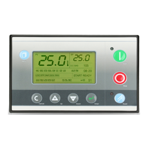
UIC-DX270 Series User’s Manual Rev 1.0 3. COMPOSITION 1) OPERATION AND DISPLAY 1-1) General composition Display: 240 X 128 Graphic LCD (LED BACKLIGHT), LED Green 1, Red 1 Keyboard: 8 main switches 1-2) Operation Start Switch: Start Stop Switch: Stop... -
Page 18: Outline
UIC-DX270 Series User’s Manual Rev 1.0 2) OUTLINE DRAWING AND PROCESSING Mount Hole : 5~6pie X 4 EA Cutout Size : 192 X 130 (mm) - 18 -... -
Page 19: Display Of Operating State
UIC-DX270 Series User’s Manual Rev 1.0 3) DISPLAY OF OPERATING STATE 4) FUNCTION OF AN OPERATION BUTTON Start or Stop Start/Stop Start when putting the start button Stop when putting the stop button Reset during trip Reset Trip having automatic... - Page 20 UIC-DX270 Series User’s Manual Rev 1.0 ON: LED is on always, OFF: LED is not on always. Low speed flickering: ON for 0.5sec, OFF for 0.5sec High speed flickering: ON for 0.1sec, OFF for 0.1sec Spot flickering: ON for 0.1sec, OFF for 4sec...
-
Page 21: Symbol Explanation
UIC-DX270 Series User’s Manual Rev 1.0 6) SYMBOL EXPLANATION 6-1) Equipment state display Start/Stop Mode State Signal LOC: Control Start/Stop button on the body RMT: Remote controlling start/stop SCH: Pre-organized start/stop on the Operation schedule Setting Menu Start/Stop Signal RUN: Start or in Process... -
Page 22: Digital Input Signal Symbol
UIC-DX270 Series User’s Manual Rev 1.0 6-2) Digital input signal symbol Symbol Description Symbol Description Over-load Main Motor Over-heat Compressor Signal Reverse-Phase Main Motor Condenser Fan Fault Signal Low-Pressure Switch Signal Flow Signal -Pump(Fan) Interlock High-Pressure Switch Signal Over-load Pump(Fan) Motor... -
Page 23: Menu Composition
UIC-DX270 Series User’s Manual Rev 1.0 4. MENU COMPOSITION 1) OPERATION AND DISPLAY Choose main menu Choose Sub menu Modify Parameter - 23 -... -
Page 24: Menu Structure
2) MENU STRUCTURE OPERATION SCHEDULE TRIP AND ALARM RUN INFO TRIP LOG 00: INLET TEMP 00: SET VALUE 00:SUN : ON ~ OFF 00: FLOW SENSING DELAY EVENT #1 01:MON : ON ~ OFF 01: OUTLET TEMP 01: RUN DIFFERENTIAL 01: FLOW SENSING HOLD EVENT #2 02: DISCHARGE GAS... -
Page 25: Menu Access Level
3) MENU ACCESS LEVEL USER 2 SERVICE 1 SERVICE 2 SERVICE 3 Access Level (CODE = 0009) (CODE = 0100) (CODE = 0119) (CODE = ****) 1. Run info. 1. Run info. 1. Run info. 1. Run info. 2. Operation 2. -
Page 26: Run Information
UIC-DX270 Series User’s Manual Rev 1.0 4) RUN INFORMATION Item Description Units Step Default View Access Inlet Temp. ℃ -40.0 70.0 View only USER 1 Outlet Temp. ℃ -40.0 70.0 View only USER 1 Discharge Gas Temp. ℃ View only... -
Page 27: Schedule Operation
UIC-DX270 Series User’s Manual Rev 1.0 Injection differential ℃ SVC1 SVC1 LCD backlight Mode On / Off USER2 USER2 ※ According to the control objects that set up in operation menus, Unit (℃,bar,%) is changed. 1) Set value: Input a standard of freezer control. -
Page 28: Trip Log
UIC-DX270 Series User’s Manual Rev 1.0 7) TRIP LOG Item Date Time Occur/Reset Event Y Y / M M / D D The name of Trip warning #1 Y Y / M M / D D The name of Trip warning #2... -
Page 29: Trip And Alarm
UIC-DX270 Series User’s Manual Rev 1.0 The state of equipment during trip 8) TRIP AND ALARM Item Description Units Step Default View Access Flow sensing delay Sec. SVC1 SVC1 Flow sensing hold Sec. SVC1 SVC1 Discharge temp over ℃ SVC1... -
Page 30: Trip Alarm Message
UIC-DX270 Series User’s Manual Rev 1.0 Stream detection operation time: Shall be OFF state during action time, and input of a stream detection switch perceives.( If it is 0 seconds, do not perceive) 2) Outlet temp freeze: A trip function runs hereafter the freezing temperature that exit temperature is excessive. - Page 31 UIC-DX270 Series User’s Manual Rev 1.0 DetectionDischarge-gas temp. > [Trip alarm setting: Excessive temperature setting of discharge-gas] Dc gas over-temp CancellationDischarge-gas temp <= [Trip alarm setting: Excessive temperature setting of discharge-gas] - 5℃ Detection exit temp. < [Trip alarm setting: An excessive freezing temperature alarm of...
-
Page 32: Extent Operating Set
UIC-DX270 Series User’s Manual Rev 1.0 9) EXTENT OPERATING SET Item Description Units Step Default View Access LOCAL / REMOTE CONTROL / Running mode LOCAL SVC1 SVC1 RESERVATION Control source IN / OUT / B4 / E-B4 / P-B4 SVC1... -
Page 33: Configure
UIC-DX270 Series User’s Manual Rev 1.0 10) CONFIGURE ※ Should change a setting number since a grasp called exactly a characteristic ※ Perfection shall be stopped, and setting is possible equipment. Item Description Units Step Default View Access Comp. start method... -
Page 34: Calibration
UIC-DX270 Series User’s Manual Rev 1.0 11) CALIBRATION Item Description Units Step Default View Access Inlet temp sensor cal ℃ -20.0 +20.0 USER 2 USER 2 Outlet temp sensor cal ℃ -20.0 +20.0 USER 2 USER 2 Discharge-gas temp cal ℃... -
Page 35: Test Mode
UIC-DX270 Series User’s Manual Rev 1.0 12) TEST MODE Accessible right: SVC1, Changeable right: SVC2 Item Description Units Step Default Manual test mode 1000 ON / OFF Cr1 capacity sol 1001 ON / OFF Cr2 capacity sol 1002 ON / OFF... -
Page 36: Factory Set
SVC3 This product has a digital control function in terms of a digital Input/Output function. When customer wants the change something, please contact to [DOTECH] company. 1) Self test: It is set ‘ON’, when taking test or delivered. 2) Log clear: Use to delete Trip Warning Background. -
Page 37: System Date/Time
UIC-DX270 Series User’s Manual Rev 1.0 14) SYSTEM DATE/TIME Date/time is used for a report of system information by trip/state report and schedule operation. Thus, it is necessary for a trouble or an abnormal condition. Please set date/time. 1) Put menu button once on the main display, see the display to set access code. -
Page 38: Installation Process
UIC-DX270 Series User’s Manual Rev 1.0 5. INSTALLATION PROCESS 1) INSTALLATION PLACE Please set this product up in the place mentioning below. ⊙ Low temperature change or normal temperature ⊙ No corrosiveness gas ⊙ No low and high humid ⊙ Low machinery vibration ⊙... -
Page 39: Electric Drawing
UIC-DX270 Series User’s Manual Rev 1.0 6. ELECTRIC DRAWING - 39 -... - Page 40 C-DX270 Ser ries User’s M Manual Rev 1.0 . SENS SOR DA 1) TEM MPERAT TURE SEN NSOR DA Discharge e-gas tempe erature senso or only. Sensor m model: DPR-T TH02-P6D10 0L*3m Use temp perature: -50 0 ~ 250 ℃ Sensor th hickness: 6m m, sensor le...
Need help?
Do you have a question about the UIC-DX270 and is the answer not in the manual?
Questions and answers